Vacuum Interrupter Contact Erosion and Maintenance Cycles in VCB Panels

In medium voltage power distribution systems, vacuum circuit breakers play a critical role in protecting electrical infrastructure from overloads and fault currents. Installed inside VCB panels, these breakers interrupt fault currents rapidly while maintaining high reliability and minimal maintenance requirements.

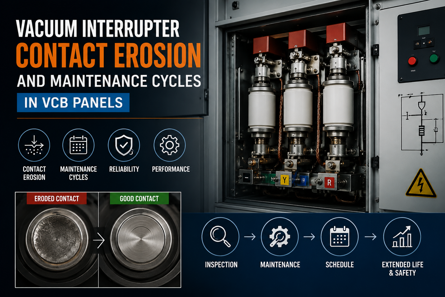
At the heart of every vacuum circuit breaker (VCB) lies the vacuum interrupter, a sealed switching device designed to extinguish electrical arcs during current interruption. While vacuum technology offers superior arc quenching characteristics, repeated switching operations gradually cause contact erosion inside the vacuum interrupter.

For electrical engineers responsible for medium voltage switchgear maintenance, understanding vacuum interrupter contact erosion and maintenance cycles in VCB panels is essential for ensuring long-term reliability and safe operation of industrial power distribution systems.

What Happens Inside the Vacuum Interrupter During Switching

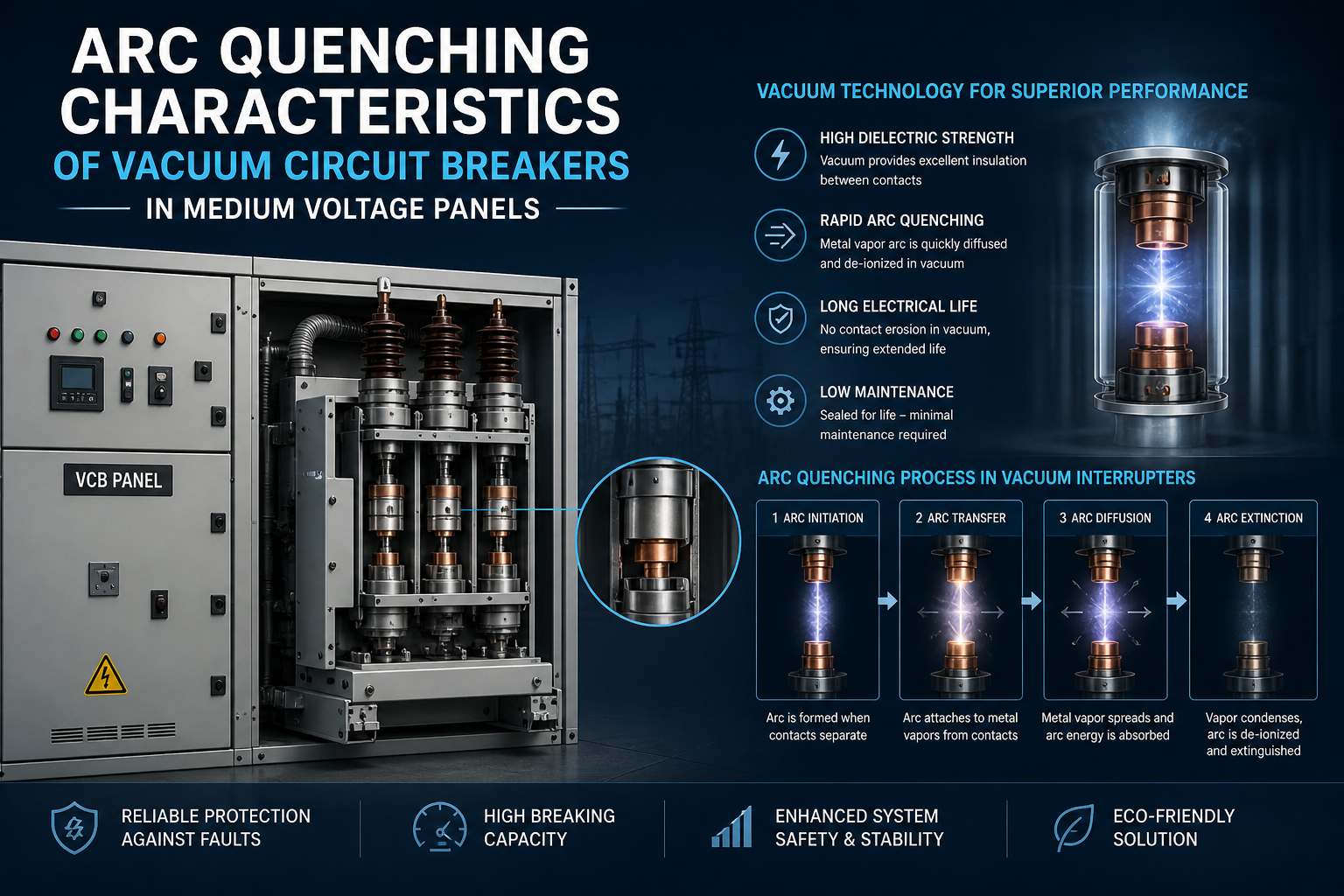
When a vacuum circuit breaker interrupts current, the breaker contacts separate inside a high-vacuum environment. Despite the vacuum conditions, an electrical arc still forms due to the vaporization of metal from the contact surfaces.

This arc consists of metal vapor plasma generated from the contact material. As the alternating current approaches its natural zero crossing, the arc collapses rapidly because the vacuum environment does not support sustained ionization.

Although the arc duration is extremely short, each interruption causes a small amount of contact material erosion. Over time, repeated switching operations gradually reduce the thickness of the contacts inside the vacuum interrupter used in VCB panels.

This process is known as vacuum interrupter contact erosion.

Contact Material Engineering in Vacuum Circuit Breakers

The performance and lifespan of vacuum interrupters in medium voltage VCB panels depend heavily on the design and composition of the breaker contacts.

Most modern vacuum circuit breakers use copper-chromium (CuCr) contact materials, which provide an optimal balance between electrical conductivity, arc resistance, and mechanical durability.

Copper ensures efficient current conduction, while chromium enhances resistance to arc erosion. During switching events, the arc moves across the contact surface rather than remaining concentrated in one location.

This arc movement distributes thermal energy more evenly, reducing localized damage and extending the operational life of the vacuum interrupter contacts.

Advanced contact geometries and magnetic field control techniques further improve the arc distribution behavior inside vacuum circuit breakers.

Key Factors That Influence Contact Erosion in VCB Panels

Although vacuum circuit breakers are known for their long mechanical life, several operational factors influence the rate of contact erosion inside vacuum interrupters.

Switching Frequency

Frequent switching operations increase the number of arc events experienced by the contacts. Industrial environments with frequent load switching may experience faster contact wear.

Interrupting High Fault Currents

Interrupting high short circuit currents generates stronger arcs and greater thermal stress on contact surfaces. Repeated fault interruptions accelerate contact erosion in VCB panels.

System Voltage and Load Conditions

Medium voltage distribution systems operating at higher voltages generate stronger arc energy during interruption events, which may contribute to increased contact wear.

Contact Material and Breaker Design

Modern vacuum circuit breaker designs incorporate optimized contact structures and magnetic arc control to minimize erosion and improve switching endurance.

Understanding these factors helps engineers predict maintenance cycles for vacuum circuit breakers in medium voltage switchgear panels.

Monitoring Contact Wear in Vacuum Circuit Breakers

Unlike oil circuit breakers, vacuum interrupters are sealed units that cannot be visually inspected internally. Instead, engineers rely on several diagnostic methods to assess contact wear in VCB panels.

Common monitoring techniques include:

  • mechanical travel measurement of breaker contacts
  • contact resistance testing
  • vacuum integrity testing of the interrupter chamber
  • breaker timing analysis during switching operations

By tracking these parameters, maintenance engineers can determine whether vacuum interrupter contacts are approaching their wear limits.

Modern medium voltage VCB panels often incorporate monitoring systems that record breaker operations and switching cycles to assist in predictive maintenance.

Maintenance Cycles for Vacuum Circuit Breakers in Medium Voltage Panels

One of the major advantages of vacuum circuit breaker technology is its relatively low maintenance requirement compared to older breaker technologies.

However, periodic maintenance remains essential to ensure safe operation of VCB panels in medium voltage power distribution systems.

Typical maintenance practices include:

  • inspection of mechanical operating mechanisms
  • lubrication of breaker operating parts
  • verification of contact travel and contact pressure
  • electrical testing of insulation and contact resistance

Maintenance intervals are typically based on number of switching operations, fault interruptions, and operating environment conditions.

For many industrial VCB panels, vacuum interrupters can withstand 10,000 to 30,000 switching operations before replacement may be required.

Reliability Benefits of Vacuum Interrupter Technology

The adoption of vacuum interrupters in medium voltage switchgear has significantly improved the reliability of modern power distribution systems.

Compared to oil circuit breakers or air circuit breakers, VCB panels provide several advantages:

  • extremely fast arc quenching
  • minimal contact wear during normal operation
  • sealed interrupter chambers that prevent contamination
  • long electrical and mechanical service life

Because of these benefits, vacuum circuit breakers have become the preferred switching technology for medium voltage power distribution panels in industrial facilities, utilities, and infrastructure projects.

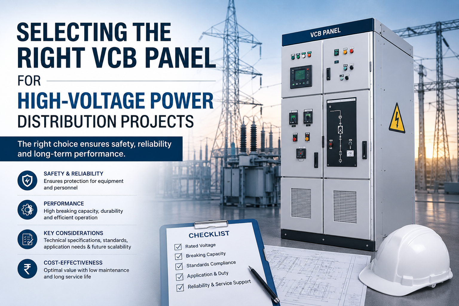
Synchro Electricals: Reliable VCB Panels for Medium Voltage Systems

Synchro Electricals manufactures advanced VCB panels designed for medium voltage power distribution networks. These panels integrate high-performance vacuum circuit breakers engineered for efficient arc interruption and long operational life.

Each VCB panel produced by Synchro Electricals is designed with durable switchgear components and robust panel construction to ensure reliable performance in demanding industrial environments.

With strong expertise in industrial electrical panels and medium voltage switchgear systems, Synchro Electricals provides dependable solutions for power distribution in manufacturing facilities, utilities, and infrastructure installations.

Sustaining Performance Through Proper VCB Maintenance

Although vacuum circuit breakers are known for their durability, monitoring vacuum interrupter contact erosion and maintenance cycles remains essential for maintaining system reliability.

By implementing regular testing, monitoring breaker operations, and following recommended maintenance schedules, industrial facilities can ensure the long-term performance of VCB panels in medium voltage power distribution systems.

Effective maintenance strategies not only extend equipment lifespan but also enhance the overall stability and safety of industrial electrical networks.

FAQs

  1. 1. What causes contact erosion in vacuum circuit breakers?

    Contact erosion occurs due to the metal vapor arc formed during current interruption inside the vacuum interrupter.

  2. 2. How long do vacuum interrupter contacts typically last?

    In most medium voltage applications, vacuum interrupters can withstand 10,000–30,000 switching operations depending on load and fault conditions.

  3. 3. How is contact wear monitored in VCB panels?

    Engineers monitor contact wear through contact resistance testing, breaker timing analysis, and measurement of contact travel.

  4. 4. Why are vacuum circuit breakers preferred in medium voltage systems?

    VCBs provide fast arc quenching, long operational life, minimal maintenance, and reliable fault interruption in medium voltage power distribution networks.

  5. 5. When should vacuum interrupters be replaced in VCB panels?

    Replacement is recommended when contact wear exceeds manufacturer limits or when diagnostic tests indicate reduced interrupter performance.

DCDB Panels in Battery Energy Storage Systems (BESS): Safe DC Power Distribution

Battery Energy Storage Systems (BESS) have become an essential component of modern power infrastructure. With the growing integration of renewable energy sources such as solar and wind, large-scale battery systems are increasingly deployed to stabilize grid operations, manage peak loads, and provide backup energy during power disturbances.

At the core of this architecture lies the DCDB panel, a specialized DC distribution board used in battery energy storage systems to manage and protect the flow of high-voltage direct current. In large energy storage installations, DCDB panels for BESS collect DC power from battery strings and safely route it to the power conversion system (PCS) that converts DC power into usable AC electricity.

Because battery energy storage systems operate with high DC voltages, large current flows, and dynamic charge–discharge cycles, the engineering of DCDB panels in BESS installations must address critical factors such as DC fault interruption, surge protection, thermal stability, and system monitoring.

Where DC Distribution Sits in the BESS Power Architecture

A battery energy storage system typically consists of multiple battery racks connected in series and parallel configurations to achieve the required voltage and capacity. These battery strings generate high-voltage DC power that must be safely aggregated before being delivered to the inverter system.

The DCDB panel in a BESS facility functions as the electrical consolidation point for these battery strings. It integrates incoming DC feeders from multiple battery racks and distributes the combined power toward the power conversion system.

Unlike traditional AC power distribution, DC power distribution in battery storage systems requires specialized engineering considerations. The absence of natural current zero-crossing in DC circuits means that fault currents behave differently, making DC fault interruption and protection coordination more complex.

As a result, DCDB panels used in battery energy storage installations must incorporate components specifically designed for high-voltage DC switching and protection.

Electrical Protection Strategy Inside BESS DCDB Panels

Because battery energy storage systems contain large amounts of stored electrical energy, any fault condition can propagate rapidly if not isolated quickly. For this reason, protection systems integrated within DCDB panels for BESS applications must respond quickly and reliably.

Protection mechanisms typically integrated in DCDB panels used in energy storage systems include:

  • DC circuit breakers capable of interrupting high DC fault currents
  • DC-rated fuses for string-level protection
  • surge protection devices (SPDs) to protect power electronics from transient overvoltages
  • DC isolators and disconnect switches for safe maintenance and emergency shutdown

These protective components ensure that faults occurring in one battery string can be isolated without affecting the entire battery energy storage power network.

Proper protection coordination within DC distribution panels for BESS is therefore essential to maintain system reliability and prevent cascading failures.

Managing High Current Flow in DC Busbar Systems

Inside DCDB panels for battery storage systems, busbars act as the main conductors carrying DC power from battery strings toward the inverter interface. Because BESS installations often operate at voltage levels between 600V and 1500V DC, the current levels inside the DC distribution board can be extremely high.

As current flows through the DC busbar system, resistive heating occurs according to electrical loss equations. Excessive heat can degrade insulation materials, affect conductor integrity, and reduce equipment lifespan.

To manage this, engineers designing DCDB panels in battery energy storage facilities must carefully evaluate:

  • busbar material conductivity
  • cross-sectional area of conductors
  • spacing between busbars
  • enclosure thermal characteristics

Proper thermal design ensures that DCDB panels handling high current loads in BESS systems maintain safe operating temperatures during both charging and discharging cycles.

Addressing DC Arc Risks in Battery Storage Systems

One of the most important safety considerations in DC power distribution for BESS installations is arc formation during switching or fault conditions.

Unlike AC circuits, DC arcs do not extinguish naturally because current does not pass through zero during the cycle. Once formed, a DC arc can persist unless interrupted by specially designed switching devices.

This makes DC-rated protection devices within DCDB panels essential for safe system operation. Engineers must ensure that all switching equipment used in BESS DC distribution boards is capable of safely interrupting DC fault currents.

Proper insulation coordination and conductor spacing inside the panel also help minimize the likelihood of arc formation during abnormal operating conditions.

Integration with Monitoring and Control Systems

Modern battery energy storage systems rely heavily on digital monitoring platforms that supervise both electrical and battery performance. The DCDB panel in BESS installations often integrates monitoring devices that provide real-time visibility into DC electrical parameters.

These monitoring systems track parameters such as:

  • DC voltage levels from battery strings
  • current flow through distribution feeders
  • temperature conditions inside the panel
  • fault conditions and protective device status

The collected data is typically transmitted to supervisory systems such as SCADA platforms or battery management systems (BMS). This integration allows plant operators to maintain full visibility of DC power distribution within the energy storage system.

Engineering Reliability for Large-Scale Energy Storage

As grid-scale battery energy storage systems continue to grow in capacity, the reliability of DC electrical infrastructure becomes increasingly important. The DCDB panel plays a crucial role in maintaining safe power flow between battery arrays and power conversion systems.

A well-designed DCDB panel for BESS applications must balance several engineering priorities: electrical protection, thermal performance, mechanical strength, and operational monitoring.

When these elements are properly integrated, the DC distribution system can support the demanding operational cycles of modern energy storage facilities while maintaining high levels of safety and reliability.

With the global expansion of renewable energy and grid stabilization technologies, DCDB panels will remain a foundational component of safe and efficient DC power distribution in battery energy storage systems.

FAQs

  1. 1. What is the function of a DCDB panel in a battery energy storage system?

    A DCDB panel collects DC power from multiple battery strings and safely distributes it to the power conversion system in a BESS installation.

  2. 2. Why is DC protection important in BESS DCDB panels?

    Battery systems contain high stored energy, so DC protection devices help isolate faults quickly and prevent damage to batteries and power electronics.

  3. 3. What voltage levels are common in BESS DC distribution systems?

    Most modern battery energy storage systems operate between 600V and 1500V DC, depending on system design.

  4. 4. Why is DC arc interruption more difficult than AC interruption?

    DC circuits do not have natural current zero-crossings, which makes extinguishing electrical arcs more challenging.

  5. 5. How are DCDB panels monitored in energy storage systems?

    Monitoring devices integrated in DCDB panels transmit electrical parameters such as voltage, current, and temperature to SCADA or battery management systems.

Selecting the Right VCB Panel for High-Voltage Power Distribution Projects

High-voltage power distribution networks used in industrial facilities, infrastructure developments, and large EPC projects require switching equipment that can safely handle high electrical loads and fault conditions. One of the most reliable technologies used in modern medium and high-voltage switchgear systems is the VCB panel (Vacuum Circuit Breaker panel).

In power transmission and EPC power distribution projects, VCB panels are responsible for switching operations, feeder protection, and isolating electrical faults within the network. Because these panels operate in demanding environments and handle voltage levels ranging from 3.3kV to 36kV, selecting the right high-voltage VCB panel is essential for ensuring safe and stable electrical infrastructure.

A properly designed VCB panel for high-voltage power distribution improves fault protection, reduces downtime, and supports the long-term reliability of power systems.

Why Vacuum Circuit Breaker Panels Are Preferred in High-Voltage Systems

Vacuum circuit breaker technology has become the industry standard for medium and high-voltage power distribution panels. Unlike oil or air circuit breakers, a vacuum circuit breaker (VCB) extinguishes electrical arcs inside a sealed vacuum interrupter.

When the breaker contacts separate during switching or fault interruption, an electrical arc forms due to the ionization of metal vapor from the contact surfaces. In a vacuum environment, however, the lack of gas molecules prevents the arc from sustaining itself. As the current reaches its natural zero crossing, the arc collapses rapidly and the vacuum regains its insulation strength.

This fast arc quenching capability of vacuum circuit breakers offers several advantages in high voltage power distribution projects, including faster fault interruption, minimal contact erosion, and longer operational life. These characteristics make VCB panels highly suitable for industrial power systems and utility distribution networks.

Matching the VCB Panel to System Voltage and Fault Levels

Selecting a high voltage VCB panel begins with evaluating the electrical characteristics of the power system. The panel must be compatible with the system voltage level and capable of handling the maximum fault current expected in the network.

Typical voltage ratings used in VCB panels for power distribution systems include 6.6kV, 11kV, 22kV, and 33kV. In addition to voltage compatibility, engineers must evaluate the short-circuit interrupting capacity of the vacuum circuit breaker.

Industrial facilities with large transformers or multiple power sources can produce high prospective fault currents. If the VCB panel short circuit rating is insufficient, the breaker may not be able to interrupt the fault safely. For this reason, proper coordination between system fault levels and breaker interrupting capacity is critical in high voltage switchgear design.

Operational Reliability and Switching Performance

Power distribution systems require frequent switching operations for load control, maintenance isolation, and fault management. The operational endurance of the vacuum circuit breaker therefore, plays an important role when selecting a VCB panel.

Modern high voltage VCB panels are designed to support thousands of switching operations while maintaining stable performance. Vacuum interrupter contacts experience minimal wear during normal switching, which contributes to the long service life of the breaker.

Two key parameters often evaluated during VCB panel selection for EPC power projects are mechanical endurance and electrical endurance. Mechanical endurance refers to the number of open–close operations the breaker mechanism can perform, while electrical endurance represents the breaker’s ability to interrupt load and fault currents repeatedly without degradation.

Reliable switching performance ensures that the VCB panel maintains consistent protection capability throughout its lifecycle.

Protection Systems Integrated in VCB Panels

Protection and control functions are essential elements of high voltage VCB panels used in power distribution networks. Modern switchgear panels incorporate advanced protection relays that continuously monitor electrical parameters.

These relays detect abnormal conditions such as overcurrent or earth faults and initiate breaker tripping to isolate the faulty section of the system. Protection functions typically integrated within VCB panels for industrial power distribution include:

  • Overcurrent and short circuit protection
  • Earth fault protection
  • Feeder protection for outgoing distribution circuits
  • Protection coordination with upstream and downstream switchgear

These protective mechanisms ensure that electrical faults are cleared quickly, preventing damage to equipment and maintaining stability within the high-voltage power distribution network.

Engineering Design and Panel Construction

Apart from electrical ratings, the mechanical construction of the VCB panel also plays a significant role in system reliability. High-voltage switchgear panels are typically designed with compartmentalized structures separating busbars, circuit breakers, and cable sections.

This arrangement improves operational safety and helps contain electrical faults within specific compartments. Proper insulation coordination, busbar spacing, and cable termination design are also critical factors considered during VCB panel engineering for power transmission projects.

Manufacturers specializing in industrial electrical panels and medium voltage switchgear, such as Synchro Electricals, focus on designing VCB panels that meet the reliability and safety requirements of high-voltage power distribution systems used in industrial plants and EPC infrastructure projects.

Ensuring Reliable Power Distribution with the Right VCB Panel

Selecting the appropriate VCB panel for high-voltage power distribution projects requires careful evaluation of system voltage, fault current levels, switching endurance, and protection coordination. Each of these factors contributes to the safe operation of the electrical network.

As industrial facilities and infrastructure projects continue to expand, high voltage VCB panels remain a fundamental component of modern power distribution systems. By choosing properly engineered vacuum circuit breaker panels, power system designers can ensure reliable switching performance, enhanced electrical protection, and long-term operational stability.

FAQs

  1. 1. What is a VCB panel used for in power distribution systems?

    A VCB panel houses vacuum circuit breakers used to control and protect medium and high-voltage power distribution networks.

  2. 2. What voltage levels are commonly used in VCB panels?

    VCB panels are commonly designed for 6.6kV, 11kV, 22kV, and 33kV power distribution systems.

  3. 3. Why are vacuum circuit breakers preferred over other breaker types?

    They provide fast arc interruption, longer service life, minimal maintenance, and reliable fault protection.

  4. 4. What protection systems are included in VCB panels?

    Typical protection systems include overcurrent protection, earth fault protection, and feeder protection relays.

  5. 5. Where are high voltage VCB panels commonly installed?

    They are widely used in power plants, substations, industrial manufacturing facilities, and large infrastructure power distribution projects.

Designing PCC Panels for Heavy Industrial Load Centers: Best Practices & Standards

Heavy industrial facilities such as steel plants, cement manufacturing units, refineries, and large process industries operate with extremely high electrical loads. These environments require robust and reliable power distribution systems capable of handling continuous operation, high current demand, and significant fault levels. At the center of such distribution networks lies the PCC panel (Power Control Center panel).

A well-engineered PCC panel for heavy industrial load centers acts as the primary interface between incoming power sources – such as transformers or generators – and multiple downstream electrical feeders. Because these panels handle large currents and complex distribution networks, following proper PCC panel design best practices is essential for ensuring electrical safety, operational reliability, and efficient power management.

Designing industrial PCC panels involves careful consideration of electrical ratings, busbar configuration, protection systems, and compliance with international electrical standards.

PCC Panels in Heavy Industrial Power Distribution

In large industrial facilities, power is typically received from high-capacity transformers and distributed across multiple sections of the plant. The PCC panel functions as the central distribution hub that manages this power flow.

From the PCC panel, electrical power is supplied to downstream panels such as MCC panels (Motor Control Centers), distribution boards, and specialized process equipment panels. Because these feeders support critical plant operations, the PCC panel must provide reliable switching, protection, and load management capabilities.

Heavy industries often operate equipment such as large motors, compressors, furnaces, and processing machinery that demand a stable and uninterrupted power supply. A properly designed PCC panel for industrial load centers ensures balanced distribution of electrical loads while maintaining protection against overloads and short circuits.

Electrical Ratings and Fault Level Considerations

One of the most important aspects of PCC panel design for heavy industrial applications is selecting the correct electrical ratings. Industrial facilities typically operate with high transformer capacities, which can result in significant short-circuit fault levels.

The PCC panel short circuit withstand rating must be capable of handling the maximum prospective fault current within the system. If the panel components are not rated properly, severe damage may occur during fault conditions.

Engineers must evaluate several parameters when determining the electrical ratings of industrial PCC panels, including transformer capacity, system voltage, and network configuration. Circuit breakers used in PCC panels must also have sufficient interrupting capacity to safely clear electrical faults.

Ensuring proper coordination between breaker ratings and system fault levels is a critical step in developing reliable power distribution infrastructure.

Busbar System Design for High Current Distribution

The busbar system inside a PCC panel carries large electrical currents from the incoming supply to outgoing feeders. Because heavy industrial plants often require high current capacities, the design of the busbar system becomes a major engineering consideration.

Copper busbars are commonly used in industrial PCC panels due to their high electrical conductivity and strong mechanical properties. The cross-sectional area of the busbar must be carefully calculated to ensure it can handle the rated current without excessive temperature rise.

Proper spacing between busbars is also essential to prevent flashover and ensure adequate insulation between phases. In many heavy industrial power control center panels, busbars are supported using insulated supports that provide both electrical insulation and mechanical stability.

Thermal management is another important factor in PCC panel design best practices. Adequate ventilation and proper panel layout help dissipate heat generated by high current flow.

Protection and Control Integration

Protection systems are a vital component of PCC panels used in heavy industrial load centers. Industrial electrical networks are exposed to various fault conditions, including overloads, short circuits, and earth faults.

To detect and isolate these faults quickly, modern PCC panels integrate advanced protection relays and circuit breakers. These devices continuously monitor electrical parameters and trip the breaker if abnormal conditions occur.

Protection schemes implemented in industrial PCC panels typically include:

  • Overcurrent protection for feeder circuits
  • Short circuit protection to isolate faults
  • Earth fault protection to detect leakage currents
  • Protection coordination with downstream MCC panels

These protection systems ensure that faults are isolated at the appropriate location, minimizing disruption to the rest of the plant.

Compliance with Electrical Standards and Safety Guidelines

Designing reliable PCC panels for heavy industrial applications also requires strict adherence to recognized electrical standards. Standards ensure that switchgear equipment meets safety and performance requirements under demanding operating conditions.

Common standards followed in PCC panel design and manufacturing include IEC 61439, IEC 60947, and relevant national electrical standards. These standards define requirements for temperature rise limits, insulation coordination, mechanical strength, and fault withstand capability.

Compliance with these standards ensures that power control center panels used in industrial load centers can operate safely even under extreme electrical conditions.

Manufacturers such as Synchro Electricals, involved in the engineering of industrial electrical panels, typically design PCC panels following these established standards to ensure reliability in high-load industrial environments.

Building Reliable Power Infrastructure for Heavy Industry

Heavy industrial facilities depend on a continuous and reliable power supply to maintain production processes. The PCC panel serves as the backbone of industrial power distribution, managing incoming electrical power and supplying it safely to various plant loads.

By following proven PCC panel design best practices, engineers can ensure that power distribution systems remain stable, protected, and capable of supporting demanding industrial operations.

Careful attention to electrical ratings, busbar configuration, protection coordination, and compliance with industry standards allows PCC panels to deliver reliable performance in heavy industrial load centers while maintaining high levels of electrical safety.

FAQs

  1. 1. What is a PCC panel used for in industrial facilities?

    A PCC panel distributes electrical power from the main transformer to various sections of an industrial plant while providing protection and switching functions.

  2. 2. Why are PCC panels important in heavy industrial load centers?

    They manage large electrical loads and ensure safe power distribution to critical equipment and downstream panels.

  3. 3. What materials are commonly used for PCC panel busbars?

    Copper busbars are widely used due to their high conductivity and ability to handle large currents.

  4. 4. What protection systems are included in PCC panels?

    Typical protection systems include overcurrent protection, short circuit protection, and earth fault protection.

  5. 5. Which standards are commonly followed in PCC panel design?

    PCC panels are typically designed according to standards such as IEC 61439 and IEC 60947 to ensure safety and reliability.

Comparing Manual vs Automatic Synchronizing Panels: What’s Best for Your Business?

In commercial power systems where multiple generators operate together, synchronizing panels play a critical role in ensuring stable and safe power distribution. These panels synchronize generator parameters such as voltage, frequency, and phase angle before connecting them to a common busbar. For facilities that rely on generator-based backup or continuous power supply, selecting the right synchronizing panel becomes an important operational decision.

Businesses typically choose between manual synchronizing panels and automatic synchronizing panels depending on their power requirements, operational complexity, and automation needs. Understanding the differences between manual vs automatic synchronizing panels helps organizations select the most suitable solution for their electrical infrastructure.

Manual Synchronizing Panels in Power Systems

A manual synchronizing panel requires an operator to monitor generator parameters and perform synchronization manually. The operator observes instruments such as voltmeters, frequency meters, and synchroscopes to ensure that the incoming generator matches the busbar conditions before closing the breaker.

Manual systems are often used in small commercial power systems where synchronization operations occur infrequently, and skilled operators are available to manage the process.

Because synchronization depends on human intervention, the process can take longer and requires careful monitoring. However, manual panels are generally simpler in design and involve lower initial investment compared to automated systems.

Automatic Synchronizing Panels for Modern Power Infrastructure

An automatic synchronizing panel uses advanced controllers and protection systems to perform generator synchronization automatically. These panels continuously monitor generator parameters and automatically adjust voltage, frequency, and load sharing before connecting generators to the electrical network.

In commercial facilities with multiple generators or critical power loads, automatic synchronization significantly improves operational efficiency. The system responds quickly to changing load conditions and can automatically start, synchronize, and share load among multiple generators.

Automation also reduces dependency on manual intervention and minimizes the risk of synchronization errors. This makes automatic synchronizing panels particularly valuable for data centers, hospitals, manufacturing facilities, and large commercial complexes where power continuity is essential.

Key Differences Between Manual and Automatic Synchronizing Panels

FeatureManual Synchronizing PanelAutomatic Synchronizing Panel
Operation MethodRequires operator to synchronize generators manuallySynchronization is handled automatically by control systems
Response TimeSlower due to manual monitoring and interventionFast synchronization with real-time controller adjustments
System ComplexitySimple design with basic instrumentsAdvanced controllers, PLCs, and protection relays
Human DependencyHigh dependency on trained operatorsMinimal human intervention required
Application SizeSuitable for small commercial power systemsIdeal for large commercial or industrial power systems
Load SharingOften manual or limitedAutomatic load sharing between generators

Choosing the Right Synchronizing Panel for Your Business

Selecting between a manual synchronizing panel and an automatic synchronizing panel depends largely on the scale and operational requirements of the power system.

Businesses operating smaller generator installations may find manual panels sufficient, particularly where synchronization operations occur rarely. However, as the complexity of the electrical network increases, automation becomes increasingly beneficial.

Modern commercial facilities often prefer automatic synchronizing panels because they provide faster generator response, improved load sharing control, and better integration with monitoring systems such as SCADA.

Manufacturers involved in electrical panel engineering, including Synchro Electricals, design synchronizing panels tailored to different power system requirements. Whether for manual or automated operations, well-designed panels help ensure safe generator synchronization and reliable power distribution.

FAQs

  1. 1. What is a synchronizing panel used for?

    A synchronizing panel ensures that multiple generators match voltage, frequency, and phase before connecting to a common electrical bus.

  2. 2. What is the main advantage of automatic synchronizing panels?

    Automatic panels synchronize generators faster and reduce the need for manual operator intervention.

  3. 3. Are manual synchronizing panels still used today?

    Yes, they are still used in smaller power systems where generator synchronization is performed occasionally.

  4. 4. Which industries use automatic synchronizing panels?

    Industries such as healthcare, data centers, manufacturing, and commercial complexes commonly use automatic synchronization systems.

  5. 5. Can synchronizing panels manage load sharing between generators?

    Yes, advanced automatic synchronizing panels can automatically balance electrical load between multiple generators.

SPD Selection and Earthing Coordination in ACDB/DCDB Panels for Solar Installations

Solar photovoltaic (PV) power plants operate in open environments where electrical systems are continuously exposed to lightning strikes, switching surges, and transient overvoltages. These events can cause severe damage to inverters, monitoring systems, and sensitive electrical components if adequate protection measures are not implemented.

In solar EPC projects, ACDB DCDB panels play a crucial role in managing power distribution between PV modules, inverters, and the grid. However, the reliability of these panels heavily depends on the correct implementation of surge protection in ACDB DCDB panels and proper earthing coordination.

Selecting the right Surge Protection Devices (SPDs) and integrating them with a well-designed grounding system ensures that transient overvoltages are safely diverted away from critical equipment. For large solar installations, proper SPD selection and earthing coordination in ACDB DCDB panels is therefore essential for long-term system stability and equipment protection.

Transient Overvoltages in Solar Power Systems

Solar plants are particularly vulnerable to electrical surges due to their extensive outdoor cable networks and elevated structures. Transient overvoltages may originate from multiple sources.

Lightning strikes are the most severe cause of surges in solar installations. Even indirect lightning strikes near a solar plant can induce high voltage spikes through electromagnetic coupling.

Other sources include switching operations within the power network, grid disturbances, and rapid changes in load conditions.

These surges propagate through DC cables, inverter terminals, and AC distribution systems. Without proper surge protection in ACDB DCDB panels, these voltage spikes can damage inverters, monitoring equipment, and control electronics.

Role of ACDB and DCDB Panels in Solar Electrical Architecture

In photovoltaic power systems, DCDB panels collect the DC output from multiple solar strings and route the combined power to the inverter. The inverter converts this DC power into AC power, which is then distributed through ACDB panels before being exported to the grid or connected loads.

Because both panels are part of the primary power path, they become critical points for installing surge protection devices.

SPDs installed in DCDB panels protect the inverter from voltage spikes originating on the DC side, while SPDs installed in ACDB panels protect the inverter and downstream equipment from grid-side surges.

Properly engineered ACDB DCDB panels for solar installations therefore integrate surge protection devices along with grounding systems to manage transient energy effectively.

Surge Protection Devices Used in ACDB DCDB Panels

Selecting the correct SPD type is a key aspect of surge protection design in solar installations. SPDs are categorized based on their surge handling capability and application environment.

Common SPD types used in solar ACDB and DCDB panels

Type 1 SPD

Type 1 SPDs are designed to handle direct lightning current impulses. They are typically installed at the main electrical service entrance where the building or plant is exposed to direct lightning strikes.

Type 2 SPD

Type 2 SPDs are the most commonly used protection devices in ACDB DCDB panels. These SPDs protect equipment from induced lightning surges and switching transients.

Type 1+2 Combined SPD

In large solar plants where lightning risk is significant, combined Type 1+2 SPDs are often installed to provide both lightning current protection and surge suppression in a single device.

Correct SPD selection depends on parameters such as maximum discharge current, nominal discharge current, system voltage, and short circuit withstand capability.

Critical Parameters for SPD Selection in Solar Panels

Selecting SPDs for ACDB DCDB panels in solar installations requires careful technical evaluation. Engineers must ensure that the SPD characteristics match the electrical properties of the PV system.

Important parameters considered during SPD selection for solar power systems include:

  • Maximum system voltage of the DC string or AC grid
  • Maximum discharge current rating (Imax)
  • Nominal discharge current (In)
  • Voltage protection level (Up)
  • Response time of the surge protection device

For DC circuits, SPDs must also be capable of handling continuous DC voltage without degradation. This is especially important in solar systems where DC voltage levels may exceed 1000V or even 1500V in utility-scale installations.

Earthing Coordination in ACDB DCDB Panels

While SPDs divert surge energy away from sensitive equipment, their effectiveness depends heavily on the earthing system of the solar plant. Without proper grounding, surge energy cannot be safely dissipated into the earth.

In solar installations, earthing coordination typically includes multiple grounding systems working together:

  • Equipment earthing for electrical safety
  • Lightning protection earthing for surge discharge
  • Functional earthing for stable system operation

The SPDs installed in ACDB DCDB panels must be connected to a low-impedance grounding network so that surge currents can flow quickly into the earth.

High earthing resistance can cause surge energy to remain within the system, increasing the risk of equipment failure.

Coordination Between SPD Placement and Grounding Layout

Effective surge protection in solar plants requires strategic placement of SPDs within the electrical network. Improper SPD placement can reduce protection effectiveness even if high-quality devices are used.

Typically, DCDB panels include SPDs installed between positive and negative conductors as well as between conductors and earth. This configuration ensures that surge currents are diverted regardless of the surge path.

Similarly, ACDB panels incorporate SPDs between phase conductors and earth, protecting the inverter and AC distribution network.

Short grounding conductors and proper bonding between earthing systems are essential to minimize impedance and allow efficient surge dissipation.

Impact of Improper Surge Protection on Solar Plants

Failure to implement proper SPD selection and earthing coordination in ACDB DCDB panels can lead to multiple operational problems in solar power plants.

Sensitive components such as inverters, monitoring equipment, and data loggers can be permanently damaged by voltage surges. Replacing these components often results in significant downtime and financial losses.

Additionally, repeated surge exposure can degrade insulation systems and reduce the lifespan of electrical equipment.

For solar EPC contractors and plant operators, proper surge protection in ACDB DCDB panels is therefore a critical design consideration that directly impacts plant reliability.

Synchro Electricals: Reliable ACDB DCDB Panels for Solar Projects

Synchro Electricals manufactures high-quality ACDB DCDB panels designed specifically for solar EPC projects and photovoltaic power plants. These panels are engineered to incorporate reliable surge protection systems and optimized earthing integration.

Each ACDB DCDB panel from Synchro Electricals is designed with proper SPD accommodation, robust enclosure construction, and electrical layouts that support safe surge energy dissipation.

With expertise in industrial electrical panels and solar power distribution systems, Synchro Electricals provides dependable panel solutions for solar installations operating in demanding environments.

Conclusion

Solar power plants operate in environments where electrical surges are unavoidable. Effective protection of critical equipment therefore, depends on proper SPD selection and earthing coordination in ACDB DCDB panels.

By integrating correctly rated surge protection devices with a well-designed grounding system, solar installations can safely manage transient overvoltages caused by lightning and switching events.

For EPC contractors and plant operators, investing in well-engineered ACDB DCDB panels with advanced surge protection systems is essential to ensure long-term reliability and uninterrupted solar power generation.

FAQs

  1. 1. Why are surge protection devices (SPDs) used in ACDB/DCDB panels for solar plants?

    SPDs protect solar inverters and electrical equipment from lightning surges and transient overvoltages by safely diverting surge energy to the earthing system.

  2. 2. What type of SPD is commonly used in ACDB and DCDB panels?

    Type 2 SPDs are commonly used for surge protection in ACDB/DCDB panels, while Type 1 or Type 1+2 SPDs may be used in areas with high lightning exposure.

  3. 3. Why is earthing coordination important for surge protection in solar installations?

    Proper earthing ensures that surge currents discharged by SPDs flow safely into the ground, preventing damage to inverters and other electrical components.

  4. 4. Where are SPDs installed in ACDB and DCDB panels?

    In DCDB panels, SPDs are installed between DC conductors and earth, while in ACDB panels, they are placed between phase conductors and earth to protect the inverter and AC distribution system.

  5. 5. What voltage levels must DC SPDs handle in solar systems?

    DC SPDs must be rated for the maximum PV system voltage, which can typically range from 600V to 1500V DC depending on the solar plant design.

Arc Quenching Characteristics of Vacuum Circuit Breakers in Medium Voltage Panels

Medium voltage power distribution systems demand switching devices that can interrupt fault currents quickly and reliably. In modern electrical infrastructure, vacuum circuit breakers (VCBs) installed in medium voltage panels have become the preferred solution for safe and efficient fault interruption. Their superior arc quenching technology allows them to extinguish electrical arcs rapidly while maintaining long operational life.

In industrial power networks, the ability to interrupt fault currents safely is critical. During switching or fault conditions, an electrical arc forms between separating contacts inside the breaker. If this arc is not extinguished immediately, it can cause severe equipment damage and compromise system stability. This is where VCB arc quenching technology offers significant advantages compared to traditional air or oil circuit breakers.

Why Arc Interruption Matters in Medium Voltage Power Distribution

In medium voltage panels, circuit breakers perform the essential task of protecting electrical systems from overloads and short circuits. When a fault occurs, the breaker contacts open to interrupt current flow. However, because current continues momentarily through ionized particles, an arc is formed between the separating contacts.

The ability to control and extinguish this arc determines the effectiveness of the circuit breaker. Poor arc control can lead to contact erosion, excessive heat generation, and even equipment failure.

Vacuum circuit breakers in VCB panels are specifically designed to handle these conditions. Their arc-quenching mechanism ensures that the arc is extinguished almost immediately, making them highly reliable for industrial power distribution systems.

The Physics Behind VCB Arc Quenching Technology

The core advantage of vacuum circuit breakers lies in the unique properties of the vacuum environment. Inside the vacuum interrupter, the pressure is extremely low—typically around 10⁻⁶ to 10⁻⁷ torr. This environment contains very few gas molecules, which significantly affects arc behavior.

When breaker contacts separate inside the vacuum interrupter, a metal vapor arc forms due to the evaporation of contact material. However, because there are almost no gas molecules to sustain ionization, the arc cannot persist for long.

As the current approaches its natural zero point in an AC waveform, the arc collapses rapidly. The vacuum environment quickly regains its insulating strength, preventing the arc from re-igniting. This process is the essence of VCB arc quenching technology.

The result is extremely fast arc interruption and minimal damage to breaker contacts.

Contact Design and Its Role in Arc Control

The effectiveness of arc quenching in vacuum circuit breakers is heavily influenced by the design of the breaker contacts. Specialized contact geometries are used to control the arc and distribute heat evenly across the contact surface.

Common contact designs used in VCB panels for medium voltage systems include:

  • Radial magnetic field contacts
  • Axial magnetic field contacts
  • Spiral slot contact structures

These designs create magnetic fields that force the arc to move across the contact surface rather than concentrating in a single spot. By distributing the arc energy, contact erosion is minimized and the breaker’s operational life is extended.

Advanced VCB arc quenching systems, therefore, combine vacuum insulation with carefully engineered contact designs to achieve efficient arc interruption.

Arc Behavior During Current Interruption

In a medium voltage vacuum circuit breaker, the arc exists only for a very short duration. As current flows through the arc, a plasma channel forms between the contacts. However, because the vacuum environment lacks sufficient ionized particles, the plasma rapidly dissipates.

The interruption process typically follows these stages:

  1. Contact separation initiates the arc formation.
  2. Metal vapor plasma forms between the contacts.
  3. Magnetic fields distribute the arc energy across the contact surface.
  4. Current reaches natural zero in the AC cycle.
  5. Arc collapses instantly due to vacuum insulation recovery.

This rapid arc extinction is what makes vacuum circuit breakers in medium voltage panels highly effective in modern electrical systems.

Performance Advantages of Vacuum Arc Quenching

The advanced arc quenching characteristics of VCB panels provide several important technical benefits in industrial power distribution systems.

Key technical advantages include:

Extremely Fast Arc Interruption
The arc is extinguished at the natural current zero, ensuring rapid fault clearing.

Minimal Contact Wear
The moving arc distributes heat across the contact surface, reducing erosion.

High Dielectric Recovery Strength
Vacuum insulation restores quickly after arc extinction, preventing restrikes.

Long Electrical and Mechanical Life
VCBs typically achieve tens of thousands of switching operations with minimal maintenance.

These characteristics make vacuum circuit breakers ideal for applications requiring reliable switching under demanding electrical conditions.

Why VCB Panels Are Preferred in Modern Medium Voltage Systems

Traditional oil circuit breakers and air circuit breakers once dominated medium voltage power distribution networks. However, these technologies required frequent maintenance and posed environmental risks.

Modern VCB panels equipped with vacuum circuit breakers offer a cleaner and more reliable alternative. Because arc quenching occurs in a sealed vacuum interrupter, there is no need for oil insulation or gas refilling.

As a result, VCB arc quenching technology has become the industry standard for medium voltage switchgear and power distribution panels used in industrial facilities, infrastructure projects, and utility networks.

Synchro Electricals: Engineering Reliable VCB Panels

Synchro Electricals manufactures advanced VCB panels designed for medium voltage power distribution systems. The company focuses on delivering robust switchgear solutions that incorporate high-performance vacuum circuit breaker technology.

Each VCB panel from Synchro Electricals is engineered with precision to ensure efficient arc interruption, reliable fault protection, and long operational life. These panels are widely used in industrial plants, infrastructure projects, and high-capacity power distribution networks.

By integrating proven VCB arc quenching technology with durable panel construction, Synchro Electricals provides dependable solutions for modern electrical systems.

Conclusion

In medium voltage electrical networks, safe and efficient fault interruption is essential for maintaining system stability. The arc quenching characteristics of vacuum circuit breakers make them one of the most reliable switching technologies used in VCB panels.

By utilizing vacuum insulation and advanced contact designs, VCB arc quenching technology allows circuit breakers to extinguish arcs quickly while minimizing wear and maintenance requirements.

For industries operating medium voltage power distribution systems, adopting VCB panels with advanced vacuum circuit breakers ensures greater reliability, improved safety, and long-term operational efficiency.

FAQs

  1. 1. What is arc quenching in a vacuum circuit breaker?

    Arc quenching in a vacuum circuit breaker refers to the rapid extinction of the electrical arc formed between separating contacts inside a vacuum interrupter during current interruption.

  2. 2. Why are vacuum circuit breakers used in medium voltage panels?

    Vacuum circuit breakers are preferred in medium voltage panels because they provide fast arc interruption, high dielectric strength, minimal maintenance, and long operational life.

  3. 3. How does a vacuum help in extinguishing the arc in VCBs?

    The vacuum environment contains very few gas molecules, so the arc cannot sustain ionization and quickly collapses when the current reaches its natural zero point.

  4. 4. What voltage range typically uses VCB panels?

    VCB panels are commonly used in medium voltage systems ranging from 3.3 kV to 36 kV in industrial power distribution and utility applications.

  5. 5. What are the advantages of VCB arc quenching technology?

    VCB arc quenching offers fast fault interruption, reduced contact wear, high insulation recovery, and reliable performance in medium voltage power distribution systems.

Load Sharing in Synchronizing Panels: Intelligent Power Balancing for Multi-DG Power Plants

Industrial facilities that rely on multi-DG power plants face a critical operational challenge – how to distribute electrical load efficiently across multiple generators. When several diesel generators operate together without proper coordination, the result can be unstable frequency, inefficient fuel usage, and uneven mechanical stress.

This is where automatic synchronizing panels play a vital role. Modern synchronizing panels integrate intelligent load sharing algorithms that automatically balance electrical demand among generators operating on the same busbar.

In large-scale power generation systems, proper load sharing in synchronizing panels ensures that each DG set contributes proportionally to the total power demand, improving efficiency and protecting expensive generator equipment.

Understanding the Load Sharing Challenge in Multi-DG Power Plants

Running a single diesel generator is relatively simple. However, when multiple generators operate simultaneously in industrial power plants, maintaining equilibrium becomes significantly more complex.

Each generator must match system parameters such as frequency, voltage, and phase angle before connecting to the power bus. Once connected, the generators must continuously adjust their output so that the electrical load is evenly distributed.

Without an effective load sharing mechanism in synchronizing panels, several operational problems can arise:

  • One DG set may become overloaded
  • Other generators may run underutilized
  • Fuel efficiency may drop significantly
  • Generator engines may experience premature wear

Advanced synchronizing panels used in power generation plants prevent these issues by implementing intelligent load distribution logic.

How Automatic Synchronizing Panels Manage Generator Coordination

A synchronizing panel acts as the control center of a multi-generator power system. It monitors electrical parameters from each generator and ensures that generators connect to the system safely.

Once synchronization is achieved, the panel’s control system manages generator output using specialized load sharing algorithms.

The panel continuously monitors parameters such as:

  • Generator real power output (kW)
  • System frequency and voltage
  • Generator engine speed
  • Power factor

Based on these readings, the automatic synchronizing panel dynamically adjusts generator performance to maintain balanced load distribution across all running DG sets.

Key Load Sharing Strategies Used in Modern Synchronizing Panels

Modern industrial synchronizing panels rely on several control methods to maintain stable generator operation. Each method is designed to ensure reliable load sharing in multi-DG power plants.

1. Droop-Based Load Sharing

The droop method is one of the most widely implemented techniques in automatic synchronizing panels. In this system, a generator’s frequency slightly decreases as its load increases.

Because every generator follows this behavior, the load naturally distributes across all DG sets connected to the bus. This method is commonly used in industrial power plants and manufacturing facilities due to its simplicity and reliability.

2. Isochronous Control for Precision Power Distribution

In facilities that demand extremely stable power – such as data centers or healthcare infrastructure – more precise control is required.

Isochronous control allows one generator to maintain system frequency while other generators share load proportionally. This approach ensures tight load regulation while maintaining stable electrical parameters across the entire system.

3. Digital Load Sharing Controllers

Modern synchronizing panels for power generation plants increasingly use microprocessor-based controllers that perform real-time load management.

These controllers communicate between generators and continuously adjust fuel injection and engine speed, ensuring optimal load balancing. Digital control systems improve both efficiency and system stability in large multi-generator installations.

Operational Advantages of Intelligent Load Sharing

Well-designed load sharing systems in synchronizing panels significantly improve generator plant performance. For industrial power facilities, these benefits directly translate into lower operating costs and improved system reliability.

Key operational advantages include:

Balanced Generator Utilization
All DG sets share electrical demand evenly, preventing overload conditions.

Improved Fuel Efficiency
Generators running at optimal load levels consume less fuel per unit of power generated.

Enhanced System Stability
Stable voltage and frequency are maintained even during sudden load changes.

Reduced Equipment Wear
Balanced load distribution minimizes mechanical stress on generator engines and alternators.

These advantages make automatic synchronizing panels with advanced load sharing algorithms essential for modern power generation systems.

Engineering Considerations for Synchronizing Panel Design

Designing synchronizing panels for multi-DG power plants requires advanced electrical engineering expertise. Panel design must ensure accurate measurement, reliable control, and strong protection mechanisms.

Critical components of a high-performance industrial synchronizing panel include:

  • Precision voltage and frequency sensors
  • Intelligent load sharing controllers
  • Programmable logic controllers (PLC)
  • Protection relays for reverse power and overload conditions
  • High-quality busbar systems

Together, these components enable reliable load sharing in synchronizing panels, ensuring smooth generator coordination in demanding industrial environments.

Synchro Electricals: Advanced Synchronizing Panel Solutions

Synchro Electricals is a trusted manufacturer of industrial synchronizing panels and generator control systems designed for reliable multi-DG power plant operations.

The company’s automatic synchronizing panels incorporate advanced control technologies and intelligent load sharing algorithms, ensuring stable generator coordination and efficient power distribution.

With deep expertise in industrial electrical panel manufacturing, Synchro Electricals delivers solutions that support power plants, infrastructure projects, manufacturing facilities, and critical power installations.

By combining engineering precision with robust panel design, Synchro Electricals helps industries maintain reliable and efficient generator synchronization and load management systems.

Final Thoughts

Operating multiple generators efficiently requires more than just connecting them to the same power bus. Proper coordination through synchronizing panels with advanced load sharing algorithms is essential for maintaining system stability and optimizing generator performance.

From droop-based control to digital load sharing systems, modern automatic synchronizing panels provide the intelligence needed to manage complex multi-DG power plants.

For industrial facilities that rely on dependable power generation, investing in high-quality synchronizing panels engineered for efficient load sharing ensures long-term operational reliability and energy efficiency.

FAQs

  1. 1. What is load – sharing in synchronizing panels?

    Load sharing in synchronizing panels ensures that multiple generators in a multi-DG power plant distribute electrical load evenly, preventing overload and improving overall power system efficiency.

  2. 2. Why are synchronizing panels important for multi-DG power plants?

    Synchronizing panels match voltage, frequency, and phase before connecting generators to the busbar, ensuring safe generator operation and stable power distribution.

  3. 3. Which load sharing method is commonly used in synchronizing panels?

    The droop control method is widely used in industrial synchronizing panels because it allows generators to naturally balance load without complex communication systems.

  4. 4. What industries use automatic synchronizing panels?

    Automatic synchronizing panels are commonly used in manufacturing plants, hospitals, data centers, power plants, and large infrastructure facilities where multiple generators operate together.

  5. 5. How do load-sharing algorithms improve generator performance?

    Advanced load-sharing algorithms optimize generator utilization, reduce fuel consumption, and maintain stable voltage and frequency in multi-generator power systems.

Welcome to Synchro Electricals

We provide trusted, high-performance electrical solutions tailored for every industry.

Apply For Job