Synchronizing Panels in Oil & Gas Facilities: Reliable Power Management for Hazardous Locations

Power reliability in the oil and gas sector isn’t just an operational requirement – it’s a safety one. Offshore platforms, refineries, LNG terminals, petrochemical complexes, upstream drilling facilities – a power interruption in any of these doesn’t just disrupt processes. It hits production targets and creates serious safety concerns simultaneously.

Most oil and gas facilities run multiple power sources to keep operations continuous – diesel generators, gas generators, utility feeders, and emergency backup systems. Managing all of that efficiently requires advanced synchronizing panels for oil and gas applications.

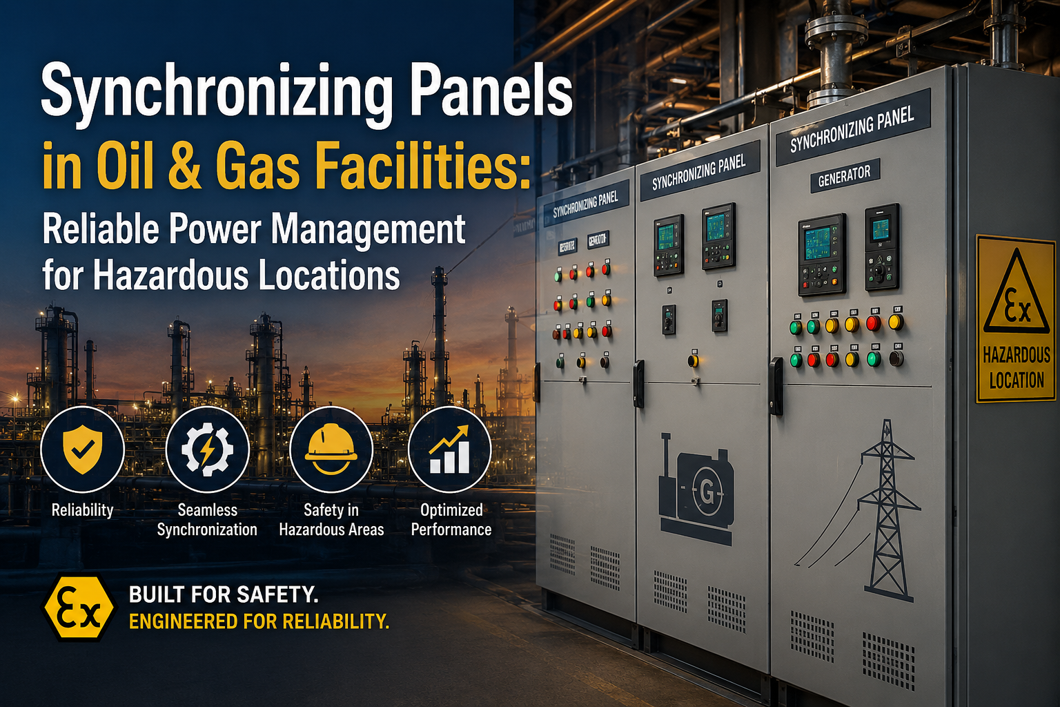
A well-designed synchronizing panel keeps multiple generators running together safely, distributes loads effectively, and maintains uninterrupted power across critical systems. In hazardous environments where reliability isn’t negotiable, these panels form an important part of the overall power management system for oil and gas facilities.

Why Power Continuity Matters More in Oil and Gas Operations

Oil and gas plants aren’t like commercial facilities. Compressors, pumps, process control systems, emergency shutdown systems, safety instrumentation – all of it depends on stable electrical power, continuously.

Even a short interruption affects production processes and triggers significant operational losses. That’s why most facilities run multiple generators in parallel rather than betting everything on a single power source.

Connecting multiple generators to a common electrical network isn’t straightforward, though. Voltage, frequency, and phase angle all have to match before a generator can be safely connected. That coordination is exactly what the generator synchronizing panel handles.

Without proper synchronization, severe electrical and mechanical stresses hit the power distribution system fast.

Operating Multiple Generators as One Power System

The core job of a synchronizing panel for oil and gas facilities is seamless operation between multiple power sources.

When an additional generator is needed, the panel monitors generator parameters continuously and adjusts them until synchronization conditions are met. Once voltage, frequency, and phase sequence match the live busbar, the breaker closes automatically, and the generator joins the system.

Modern automatic synchronizing panels also handle load distribution between generators — a process known as load sharing. This prevents one generator from running hard while others sit underutilised.

For refineries, offshore platforms, and petrochemical plants where power demand shifts throughout the day, effective load sharing improves fuel efficiency and extends generator life.

Designing Synchronizing Panels for Hazardous Locations

Electrical equipment in oil and gas facilities has to perform reliably in some of the harshest industrial conditions that exist. Explosive atmospheres, corrosive environments, extreme temperatures, continuous vibration – all of it influences how equipment gets designed.

Synchronizing panels used in hazardous locations are engineered with that reality built in from the start.

Key design requirements typically include:

  • Integration with hazardous area electrical systems
  • Robust enclosure construction
  • High-reliability control components
  • Redundant power management architecture
  • Advanced protection and monitoring systems

Depending on facility classification, synchronizing panels may also interface with explosion-proof equipment and hazardous area instrumentation. That scope makes oil and gas synchronizing panels a different animal entirely compared to standard commercial generator control panels.

SCADA Integration and Centralized Power Management

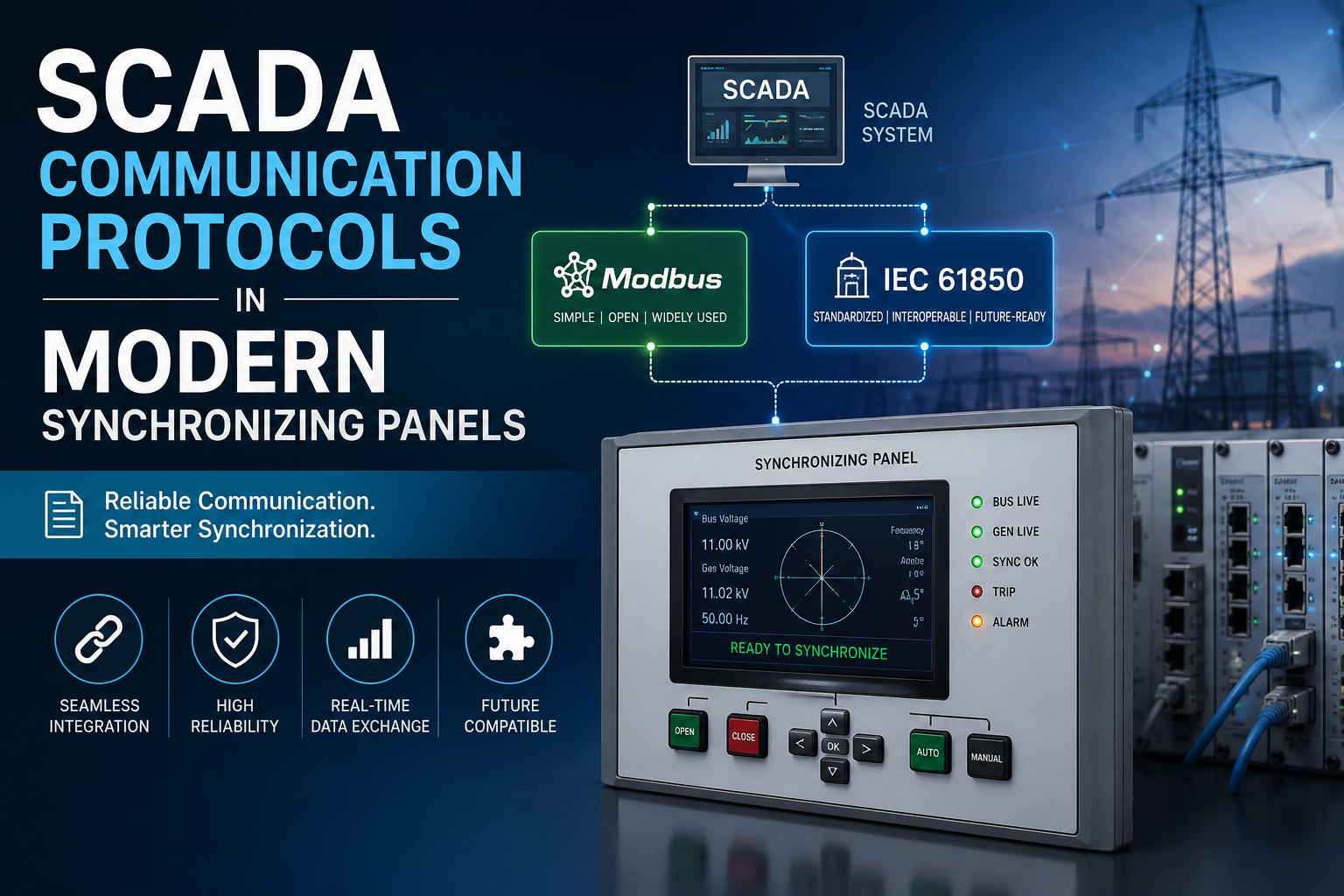
Modern oil and gas facilities run on automation and centralised monitoring. Synchronizing panels for oil and gas applications are now routinely integrated with plant-wide SCADA and distributed control systems (DCS).

That integration gives operators real-time visibility across:

  • Generator loading
  • Busbar status
  • Breaker position
  • Fuel consumption trends
  • Power quality parameters

Informed decisions get made faster when the data is all in one place. Synchronizing panels with SCADA integration also support remote operation, event logging, alarm management, and predictive maintenance programs – capabilities that matter a great deal in remote or unmanned installations.

Protection Strategies for Critical Power Systems

Electrical faults in oil and gas environments need to be detected and isolated quickly. Letting a fault develop in a critical power system isn’t an option.

Modern generator synchronizing panels carry multiple protection functions built specifically for these applications – protecting generators, switchgear, and connected loads from abnormal conditions before they escalate.

Protection schemes commonly built into oil and gas synchronizing panels include overcurrent protection, reverse power protection, under-frequency protection, over-voltage protection, and busbar protection.

Combined with intelligent control algorithms, these protection systems maintain stability across the entire industrial power distribution network.

Engineering Synchronizing Panels for Demanding Applications

At Synchro Electricals, we design and manufacture synchronizing panels for industrial power management applications across demanding sectors, including oil and gas, infrastructure, utilities, and process industries.

Our engineering focus sits on reliable generator synchronization, accurate load sharing, advanced protection coordination, and seamless SCADA integration. Robust panel construction combined with intelligent control technology is what delivers dependable power management in environments where reliability is critical, and failure isn’t an acceptable outcome.

The Backbone of Reliable Power Generation

Oil and gas facilities run around the clock, often in remote and unforgiving locations where power reliability simply cannot be compromised. Synchronizing multiple generators, distributing load efficiently, and responding quickly to changing operating conditions – that’s what keeps continuous production possible.

It’s why synchronizing panels for oil and gas facilities remain a key component of modern power management systems. Safe generator operation, intelligent load sharing, centralised control – these panels deliver the reliability that hazardous industrial locations demand.

FAQs

  1. 1. What is the purpose of a synchronizing panel in an oil and gas facility? 

    It safely connects multiple generators to a common busbar and manages load sharing between power sources – keeping the facility’s electrical system stable and continuous.

  2. 2. Why are synchronizing panels important in hazardous locations? 

    Because power failures in these environments don’t just cost money – they affect safety. These panels keep critical equipment running without interruption in conditions where that matters most.

  3. 3. Can synchronizing panels support automatic load sharing?

    Yes. Modern automatic synchronizing panels continuously balance electrical loads across multiple generators without manual intervention.

  4. 4. Are synchronizing panels integrated with SCADA systems?

    Most modern synchronizing panels support full SCADA and DCS integration for centralised monitoring, remote operation, and alarm management.

  5. 5. Where are synchronizing panels commonly used in the oil and gas sector? 

    Refineries, offshore platforms, LNG terminals, petrochemical plants, drilling facilities, and pipeline infrastructure – anywhere multiple power sources need to be managed reliably.

Capacitor Bank Switching Transients and Harmonic Mitigation in APFC Panels

Power factor correction has become a standard requirement across industrial plants, commercial buildings, utilities, and infrastructure projects. APFC panels (Automatic Power Factor Correction Panels) are designed to improve power factor and reduce utility penalties, but their performance depends heavily on how they interact with the electrical network.

In modern facilities where VFDs, UPS systems, servo drives, solar inverters, and automation equipment are common, simply installing capacitor banks is no longer enough. Switching transients and harmonic distortion both need to be addressed for the system to hold up long-term. That’s what makes APFC harmonic mitigation an important consideration in modern power distribution systems — not a nice-to-have, but part of getting the design right.

The Instant Impact of Capacitor Bank Switching

Every time a capacitor bank switches ON inside an APFC panel, a sudden charging current rushes into the capacitor. That surge creates a short-duration electrical disturbance — a switching transient.

The event itself lasts a fraction of a second. The problem is what that voltage and current spike does to sensitive equipment connected elsewhere on the network. In large industrial facilities running multiple capacitor stages, frequent switching adds up. Contactors, capacitors, and protection devices all absorb that stress over time.

This is why switching device selection and capacitor bank configuration get careful attention when engineers are designing industrial APFC panels.

Why Harmonics and APFC Panels Must Be Considered Together

Most industrial and commercial facilities today run a substantial number of non-linear loads. Variable frequency drives, rectifiers, UPS systems, CNC machines – all of them generate harmonic currents that distort the normal power waveform.

Those harmonics and capacitor banks don’t coexist quietly.

Capacitors naturally attract higher-frequency currents, which puts them directly in the path of harmonic overload. Under certain conditions the electrical system hits resonance, and when that happens, current through the capacitor bank climbs to levels it was never designed for. Overheating follows. Then capacitor failure, nuisance tripping, and shortened panel life.

This is why modern APFC panel design can’t focus only on reactive power compensation. Power quality and harmonic distortion have to be part of the same conversation.

Identifying Harmonic Risks Before They Become Problems

Before specifying an automatic power factor correction panel, engineers typically run a power quality assessment of the facility. The goal is to find out whether standard capacitor banks are appropriate or whether harmonic levels in the system demand additional mitigation.

That assessment usually covers:

  • Total Harmonic Distortion (THD) levels
  • Type of connected loads
  • Existing power factor performance
  • System short-circuit capacity
  • Capacitor bank sizing requirements

Working through this upfront is what prevents the APFC panel from creating resonance conditions in the very network it was installed to improve.

How Detuned Reactors Protect Capacitor Banks

The most widely used solution for harmonic mitigation in APFC panels is the detuned reactor.

Connected in series with the capacitor bank, a detuned reactor shifts the resonance frequency away from the dominant harmonics present in the system. Instead of the capacitors amplifying harmonic currents, the circuit limits their impact before damage occurs.

The practical benefits stack up:

  • Improved capacitor life
  • Reduced thermal stress
  • Better power quality
  • Lower risk of resonance
  • Enhanced reliability of APFC systems

For manufacturing plants, commercial complexes, and infrastructure facilities carrying significant non-linear loads, detuned APFC panels are typically the right call rather than the cautious one.

Designing APFC Panels for Modern Industrial Applications

Today’s industrial APFC panels have to do more than correct power factor. System stability, equipment protection, and harmonic management all sit inside the same design brief.

At Synchro Electricals, capacitor bank sizing, harmonic levels, switching frequency, and power quality requirements all feed into how we design APFC panels for industrial power distribution systems. Power factor correction should improve the network, not introduce new problems into it.

Proper switching technology combined with effective harmonic mitigation strategies is what allows APFC panels to perform reliably over years of operation in demanding industrial environments — not just at commissioning.

Conclusion

Capacitor banks remain essential for improving power factor and reducing energy losses. But the way they interact with harmonics can’t be treated as a secondary concern. Without proper engineering, switching transients and resonance conditions quietly degrade both the APFC panel and the wider electrical system around it.

Careful analysis, sound capacitor bank design, and detuned reactors for harmonic mitigation are what allow facilities to achieve genuine power factor correction without paying for it in power quality.

As industrial electrical networks keep evolving, APFC harmonic mitigation, reliable capacitor bank switching, and intelligent panel design will stay at the centre of efficient and stable power distribution — because the loads driving harmonic distortion aren’t going away.

FAQs

  1. 1. What causes switching transients in APFC panels? 

    When capacitor banks are energised or disconnected, a sudden surge of charging current creates temporary voltage and current disturbances in the network. That’s the switching transient.

  2. 2. Why do harmonics affect capacitor banks? 

    Capacitors pull in higher-frequency harmonic currents naturally. In a harmonic-rich environment that leads to overheating, resonance conditions, and capacitor failure well ahead of design life.

  3. 3. What is harmonic mitigation in APFC panels?

    It’s the use of solutions like detuned reactors to reduce harmonic distortion and protect capacitor banks from the resonance and thermal stress that harmonics cause.

  4. 4. What is a detuned APFC panel? 

    A panel that combines capacitors and series-connected reactors to shift the resonance frequency away from dominant harmonics – improving power quality and protecting the capacitor bank in environments where harmonic levels are significant.

  5. 5. Where are APFC panels commonly installed?

    Manufacturing plants, commercial buildings, utility facilities, infrastructure projects, and industrial power distribution systems – anywhere reactive power compensation and power factor correction are required.

Electrical Panel Earthing Design and Ground Fault Protection Methods

A well-designed electrical system is only as safe as its grounding and fault protection strategy. Circuit breakers and protection relays get most of the attention during panel design, but electrical panel earthing design is what actually provides a safe path for fault currents and keeps both equipment and personnel out of danger.

In utilities, infrastructure projects, manufacturing facilities, and commercial installations, electrical control panels are critical points of power distribution and system control. A ground fault in a panel without an effective earthing system means fault current starts finding its own way to earth – through equipment frames, enclosures, cable trays, anything conductive nearby. That’s when things get dangerous.

This is why electrical panel earthing design and ground fault protection methods are treated as non-negotiable requirements in modern power systems engineering.

When Electricity Finds the Wrong Path

Normal operation is simple enough – current flows through designated conductors and returns through the intended circuit path. A ground fault is what happens when that current escapes. It moves toward earth through equipment frames, panel enclosures, cable trays, or whatever conductive structure is closest.

Even a relatively small ground fault creates dangerous touch voltages on metallic surfaces. In higher-capacity systems, the fault currents involved are large enough to cause serious damage to switchgear, cables, and electrical control panels.

An effective electrical panel grounding system gives fault current a low-resistance path to earth – controlled, intentional, and fast enough that protective devices can detect and clear the fault before it develops further. Without that, protective devices may not operate correctly, and hazardous conditions persist.

Earthing Is More Than Connecting a Wire to the Ground

A lot of installations treat earthing as a single connection to a ground rod. That’s not earthing design — that’s a starting point at best.

Proper electrical panel earthing design requires a coordinated approach across multiple grounding components. Inside an electrical control panel, every exposed metallic part needs to be bonded together and tied into the facility’s earthing network. The result is an equipotential system that keeps voltage differences under control during fault conditions.

How well that system performs depends on soil resistivity, conductor sizing, grounding electrode configuration, and the integrity of bonding throughout the installation. Poor grounding raises system impedance, slows down fault current return, and delays fault clearing – all of which make a dangerous situation worse.

Designing Earthing Systems for Reliable Fault Current Dissipation

Earthing system design starts with one question: what is the maximum fault current this installation could see? Grounding conductors have to carry that current safely for as long as it takes protective devices to operate.

Engineers typically work through:

  • Fault current levels within the electrical network
  • Ground conductor sizing requirements
  • Earthing electrode resistance values
  • Bonding between panel components and structural elements

A properly designed grounding system improves safety and adds to the overall reliability of electrical control panels used in utility and infrastructure projects. For critical installations – substations, water treatment facilities, transportation infrastructure – achieving low earth resistance values isn’t optional, it’s a core design objective.

How Ground Fault Protection Complements Earthing Design

Earthing handles the fault current once a fault exists. Ground fault protection is what catches it early.

Modern electrical control panels incorporate ground fault protection schemes that monitor current flow continuously. When leakage current appears, the protection system acts before the fault grows into something larger.

Common ground fault protection methods in use today include:

  • Residual current monitoring
  • Earth fault relays
  • Ground fault circuit interrupters (GFCI)
  • Differential protection systems

Which method gets selected depends on voltage level, system configuration, and the operational demands of the specific installation. The point is that earthing systems and ground fault protection devices have to work together – one provides the path, the other triggers the response. Neither does the full job alone.

The Challenge of Ground Faults in Large Infrastructure Projects

Utilities and infrastructure facilities run extensive electrical networks across large geographic areas. Long cable runs, multiple distribution points, and varying soil conditions all make grounding systems considerably more complex than in a standard commercial installation.

Ground fault protection in these environments requires careful coordination so that the protective device closest to the fault operates first. That selectivity matters – it contains the problem, keeps healthy sections of the network running, and avoids shutdowns that affect far more than the faulted circuit.

As infrastructure projects rely more heavily on automation and digital control systems, effective electrical panel grounding and protection systems become even more critical. Sensitive electronics can be affected by grounding issues well before any major fault occurs, which means problems show up in the control system before they’re traceable to a grounding deficiency.

Building Safer Electrical Control Panels

At Synchro Electricals, reliable earthing is a core part of electrical panel performance — not a compliance checkbox at the end of a project. During the design of electrical control panels, our engineering team evaluates grounding arrangements, conductor sizing, bonding requirements, and protection coordination to ensure fault current is managed safely from the start.

Integrating effective electrical panel earthing design with appropriate ground fault protection methods is how we deliver panels that hold up operationally and electrically across demanding utility and infrastructure applications.

A Foundation for Electrical Safety

Most electrical problems that could have been prevented trace back to grounding issues that nobody caught until a fault made them obvious. A properly engineered electrical panel earthing system gives fault current somewhere safe to go, protective devices something to work with, and personnel a meaningful layer of protection.

Pair that with well-coordinated ground fault protection methods and the electrical control panel holds up – under normal conditions and abnormal ones. For utilities, infrastructure projects, and industrial facilities, getting grounding right from the design stage remains one of the highest-value decisions in the entire electrical system.

FAQs

  1. 1. What is the purpose of earthing in an electrical control panel?

    Earthing gives fault current a safe, controlled path to ground – protecting equipment from damage and keeping personnel away from dangerous touch voltages.

  2. 2. Why is electrical panel earthing design important?

    Because a poorly designed earthing system slows fault clearing, raises touch voltage risks, and undermines the reliability of the entire panel. Getting it right at the design stage prevents problems that are much harder to fix later.

  3. 3. What causes a ground fault in an electrical system?

    A ground fault happens when current leaves its intended path and flows to earth through equipment, exposed metal parts, or structural elements that weren’t designed to carry it.

  4. 4. What devices are used for ground fault protection?

    Earth fault relays, residual current devices, GFCIs, and differential protection systems are the most common. Selection depends on the voltage level and configuration of the specific installation.

  5. 5. How does grounding improve electrical panel safety?

    It gives fault current a defined, low-resistance path back to earth, which lets protective devices operate quickly, isolate the fault, and stop the hazardous condition before it causes harm.

Busbar Material Selection and Current Carrying Capacity Calculations in Power Distribution Panels

In modern power systems engineering, the performance and safety of power distribution panels depend heavily on the design of the busbar system. Busbars act as the primary electrical conductors inside switchboards and distribution panels, carrying large currents from incoming feeders to outgoing circuits.

Selecting the correct busbar material and performing accurate busbar current-carrying capacity calculations are critical design tasks in industrial electrical engineering. Poor busbar design can lead to overheating, voltage drop, mechanical deformation, and even catastrophic panel failures.

For engineers designing industrial power distribution panels, understanding the electrical, thermal, and mechanical characteristics of busbars is essential for ensuring reliable power delivery in high-load environments.

The Electrical Backbone of Power Distribution Panels

Inside every industrial power distribution panel, busbars function as the central pathway through which electrical energy flows. Unlike cables, busbars provide a rigid conductor structure that supports high current capacity with lower impedance and improved thermal performance.

Busbars distribute power between key components such as:

  • Incoming circuit breakers
  • Outgoing feeder breakers
  • protection relays
  • switchgear assemblies

Because these conductors carry large currents continuously, their design must ensure both efficient current transfer and thermal stability. This makes busbar material selection and current-carrying capacity calculations fundamental aspects of power distribution panel engineering.

Copper vs Aluminum: Engineering Considerations in Busbar Material Selection

One of the first design decisions in busbar system design for power distribution panels involves choosing the appropriate conductor material. The two most commonly used materials are copper busbars and aluminum busbars.

Copper Busbars

Copper is widely used in high-performance power distribution panels because of its excellent electrical conductivity and mechanical strength.

Key technical characteristics include:

  • High electrical conductivity (~58 MS/m)
  • Superior thermal conductivity
  • High short circuit withstand capability
  • Compact busbar dimensions for the same current rating

Because of these advantages, copper busbars are commonly used in high-current industrial distribution panels and critical electrical infrastructure.

Aluminum Busbars

Aluminum busbars are sometimes selected where cost and weight reduction are priorities.

Important characteristics include:

  • Lower density compared to copper
  • Reduced material cost
  • Larger cross-sectional area required for the same current capacity

Although aluminum is less conductive than copper, properly designed aluminum busbar systems can still provide reliable performance in many power distribution applications.

Current Carrying Capacity Calculations in Busbar Design

The busbar current-carrying capacity, often referred to as ampacity, determines how much current the busbar can safely conduct without exceeding permissible temperature limits.

Busbar sizing calculations consider multiple thermal and electrical parameters to ensure safe operation.

Key parameters used in busbar current calculations include:

  • Rated current of the power distribution system
  • Ambient temperature within the electrical panel
  • Permissible temperature rise of the conductor
  • Busbar material resistivity
  • Installation configuration and spacing

As current flows through the busbar, electrical resistance generates heat according to I²R losses. If the busbar cross-sectional area is insufficient, excessive heating can occur, which may damage insulation and reduce system reliability.

Therefore, accurate busbar current capacity calculations ensure that power distribution panels operate within safe thermal limits.

Thermal Performance and Heat Dissipation in Busbar Systems

Thermal management is a critical aspect of busbar design in power distribution panels. High current flow results in resistive heating, and if heat is not dissipated effectively, busbar temperatures may exceed safe operating limits.

Engineers, therefore evaluate the thermal equilibrium of busbars by considering:

  • convection cooling inside the panel enclosure
  • Radiation heat transfer between conductors
  • airflow within the switchgear cabinet

In many industrial power distribution panels, busbars are spaced strategically to allow sufficient airflow and reduce heat accumulation.

Proper busbar layout design therefore, contributes significantly to maintaining safe operating temperatures under full load conditions.

Mechanical Strength and Short Circuit Withstand Capability

Busbars inside power distribution panels must also withstand the mechanical forces generated during short circuit conditions.

When fault currents flow through conductors, powerful electromagnetic forces are generated between busbars. These forces can cause bending, vibration, or displacement if the busbars are not properly supported.

Therefore, busbar design for industrial distribution panels includes structural considerations such as:

  • rigid busbar supports
  • adequate spacing between phases
  • insulation barriers
  • high mechanical strength materials

These design features ensure that the busbar system can withstand both thermal stress and mechanical stress during fault events.

Voltage Drop and Efficiency Considerations

Another important factor in busbar current calculations is voltage drop. Excessive voltage drop across busbars can reduce the efficiency of the power distribution panel and affect downstream equipment performance.

Busbar resistance depends on:

  • conductor material
  • cross-sectional area
  • length of the conductor

By increasing the busbar cross-sectional area or selecting materials with higher conductivity, engineers can reduce voltage losses and improve overall system efficiency.

Efficient busbar system design in power distribution panels therefore supports stable voltage delivery across the electrical network.

Synchro Electricals: Precision-Engineered Power Distribution Panels

Synchro Electricals specializes in designing and manufacturing high-quality power distribution panels with optimized busbar systems. The company focuses on engineering panels that support reliable current flow, efficient heat dissipation, and strong short circuit withstand capability.

Each power distribution panel from Synchro Electricals is developed with carefully calculated busbar current-carrying capacity and material selection, ensuring dependable performance in demanding industrial environments.

With expertise in power systems engineering and industrial electrical panel manufacturing, Synchro Electricals provides robust electrical solutions that support safe and efficient power distribution across multiple industries.

Reliable Busbar Design as the Foundation of Electrical Panel Performance

The reliability of any power distribution panel ultimately depends on the quality of its busbar system. Proper busbar material selection and current-carrying capacity calculations ensure that electrical panels can safely handle high load currents without overheating or mechanical instability.

By carefully balancing electrical conductivity, thermal performance, and structural strength, engineers can design busbar systems that support long-term reliability in industrial power distribution networks.

For modern power systems, accurate busbar current calculations and optimized busbar design remain essential for building safe, efficient, and durable electrical infrastructure.

FAQs

  1. 1. What is a busbar in a power distribution panel?

    A busbar is a conductive metal strip used in power distribution panels to carry and distribute large electrical currents between incoming and outgoing circuits.

  2. 2. Which material is commonly used for busbars in electrical panels?

    Copper and aluminum are the most commonly used busbar materials, with copper offering higher conductivity and mechanical strength.

  3. 3. How is busbar current carrying capacity calculated?

    Busbar current capacity is calculated based on conductor cross-sectional area, material conductivity, permissible temperature rise, and ambient operating conditions.

  4. 4. Why is busbar sizing important in power distribution panels?

    Proper busbar sizing prevents overheating, reduces voltage drop, and ensures safe operation of the electrical distribution system.

  5. 5. What factors influence busbar performance in electrical panels?

    Material selection, cross-sectional area, thermal conditions, mechanical strength, and short circuit withstand capability all influence busbar performance.

SCADA Communication Protocols in Modern Synchronizing Panels (Modbus / IEC-61850)

In today’s smart power plants and utility-scale power generation systems, synchronizing panels are no longer standalone control units. They are integrated into plant-wide SCADA (Supervisory Control and Data Acquisition) systems that enable centralized monitoring, automation, and real-time control of generators, switchgear, and power distribution infrastructure.

Modern SCADA synchronizing panels rely on industrial communication protocols to exchange operational data between generator controllers, PLCs, protection relays, and supervisory control systems. Among the most widely implemented protocols in synchronizing panels are Modbus communication protocols and IEC-61850 substation communication standards.

For power plants operating multiple generators and complex electrical networks, the implementation of reliable SCADA communication protocols in synchronizing panels ensures seamless generator coordination, faster fault diagnostics, and improved operational efficiency.

The Digital Layer of Generator Synchronization Systems

Traditional synchronizing panels primarily performed generator synchronization functions such as voltage matching, frequency matching, and phase alignment before connecting generators to the busbar.

However, modern power plants demand far greater operational visibility. Operators must continuously monitor generator parameters such as:

  • Real power output (kW)
  • Reactive power (kVAR)
  • Voltage and frequency stability
  • Load sharing between generators
  • Breaker status and synchronization events

To achieve this level of control, synchronizing panels in smart power plants integrate with SCADA platforms through industrial communication networks.

These SCADA-enabled synchronizing panels transmit operational data to control rooms, enabling centralized supervision of generator systems across large industrial facilities and utility networks.

Communication Architecture in SCADA Synchronizing Panels

In modern power generation facilities, synchronizing panels form a critical node within the SCADA communication architecture. Multiple intelligent devices inside the panel communicate with each other through industrial protocols.

Typical devices connected within a SCADA synchronizing panel network include:

  • Generator controllers
  • PLC-based synchronizing systems
  • protection relays
  • energy meters
  • circuit breaker monitoring modules
  • SCADA gateways

These devices continuously exchange operational data with the central SCADA server, enabling real-time visualization of generator performance and electrical system status.

Industrial communication protocols such as Modbus RTU, Modbus TCP/IP, and IEC-61850 enable this seamless integration between synchronizing panels and SCADA systems.

Modbus Communication Protocol in Synchronizing Panels

One of the most widely used industrial protocols in SCADA synchronizing panels is Modbus. Originally developed for industrial automation systems, Modbus remains a reliable communication standard for exchanging data between electrical devices.

In synchronizing panels, Modbus communication protocols allow generator controllers and protection relays to transmit operational data to SCADA systems.

Two common variants of Modbus are used in power generation applications:

Modbus RTU

Modbus RTU operates over serial communication networks such as RS-485. It is widely used in industrial environments due to its simplicity, reliability, and ability to connect multiple devices on a single communication bus.

In generator synchronizing panels, Modbus RTU is often used for communication between PLC controllers, protection relays, and digital meters.

Modbus TCP/IP

Modbus TCP/IP operates over Ethernet networks, enabling faster communication and integration with modern SCADA platforms.

In large power plants and smart utility infrastructures, Modbus TCP allows synchronizing panels to communicate directly with SCADA servers, data historians, and remote monitoring systems.

The simplicity and interoperability of Modbus communication protocols make them highly suitable for synchronizing panel applications.

IEC-61850: Advanced Communication for Smart Substations

While Modbus remains widely used, many modern smart power plants and utility substations are adopting IEC-61850 communication protocols for advanced automation.

IEC-61850 is an international standard specifically developed for substation automation systems and smart grid communication.

Unlike traditional communication protocols, IEC-61850 uses object-oriented data models and high-speed Ethernet communication, enabling faster and more structured data exchange between intelligent electronic devices (IEDs).

In synchronizing panels integrated with smart grid systems, IEC-61850 enables several advanced capabilities:

  • high-speed peer-to-peer communication between protection devices
  • event-driven messaging through GOOSE communication
  • standardized device data models for interoperability
  • improved scalability for complex electrical networks

Because of these features, IEC-61850 is increasingly used in modern SCADA synchronizing panels deployed in large utility power plants.

Data Visibility and Remote Control in Smart Power Plants

Integrating SCADA communication protocols with synchronizing panels significantly enhances operational visibility across power generation facilities.

Operators can remotely monitor generator parameters such as:

  • generator loading and load sharing status
  • synchronization events and breaker operation
  • alarm conditions and protection trips
  • power quality parameters

Through SCADA interfaces, engineers can also perform remote commands such as generator start/stop operations, load adjustments, and breaker control.

This level of automation is essential for smart power plants and distributed energy systems, where centralized monitoring improves both reliability and operational efficiency.

Reliability and Cybersecurity Considerations

Because SCADA synchronizing panels operate within critical power infrastructure, communication reliability and cybersecurity are essential design considerations.

Communication networks must ensure:

  • low latency data transmission
  • redundancy for communication links
  • secure network access control
  • protection against cyber threats

Modern IEC-61850-based power automation systems often incorporate secure Ethernet networks and network segmentation to protect critical control systems.

Ensuring secure and reliable SCADA communication in synchronizing panels is therefore essential for maintaining the stability of power generation systems.

Synchro Electricals: Synchronizing Panels for Smart Power Systems

Synchro Electricals designs advanced synchronizing panels engineered for modern power generation facilities and smart utility infrastructure. These panels are built to support seamless integration with SCADA communication systems using industrial protocols such as Modbus and IEC-61850.

Each synchronizing panel from Synchro Electricals is designed to support reliable generator synchronization, intelligent load sharing, and real-time communication with supervisory control systems.

With strong expertise in industrial electrical panel manufacturing and power system automation, Synchro Electricals provides robust solutions for smart power plants, distributed generation facilities, and utility-scale power networks.

Intelligent Communication as the Foundation of Modern Power Control

As power generation systems become more complex and interconnected, communication between electrical devices becomes increasingly important.

By integrating SCADA communication protocols such as Modbus and IEC-61850, modern synchronizing panels enable centralized monitoring, advanced automation, and improved generator coordination.

For smart power plants and utility infrastructures, deploying SCADA-enabled synchronizing panels with robust communication protocols ensures greater reliability, faster fault response, and efficient management of power generation assets.

FAQs

  1. 1. What is a SCADA synchronizing panel?

    A SCADA synchronizing panel is a generator control panel integrated with a SCADA system to monitor and control generator synchronization, load sharing, and breaker operations remotely.

  2. 2. Why are communication protocols used in synchronizing panels?

    Communication protocols allow synchronizing panels to exchange real-time data with SCADA systems, enabling centralized monitoring and control of generator operations.

  3. 3. What is the difference between Modbus and IEC-61850?

    Modbus is a simple industrial communication protocol widely used for device communication, while IEC-61850 is an advanced standard designed specifically for smart substations and power system automation.

  4. 4. Which protocol is commonly used in synchronizing panels?

    Modbus RTU and Modbus TCP/IP are commonly used in synchronizing panels, while IEC-61850 is increasingly adopted in modern smart grid and utility applications.

  5. 5. How does SCADA integration improve generator synchronization systems?

    SCADA integration allows operators to monitor generator performance, control synchronization operations remotely, and quickly detect faults in power generation systems.

Arc Flash Hazard Analysis in Industrial PCC Panels and Mitigation Techniques

Industrial manufacturing facilities operate large electrical distribution networks where PCC panels (Power Control Center panels) manage high-current power flow from transformers to multiple downstream feeders. In such environments, one of the most severe electrical safety risks is an arc flash event inside electrical panels.

An arc flash occurs when electrical current deviates from its intended path and travels through ionized air between conductors or between a conductor and ground. The resulting arc produces extremely high temperatures, intense light, and explosive pressure waves that can severely damage equipment and pose serious danger to personnel.

For this reason, arc flash hazard analysis in industrial PCC panels has become an essential part of modern industrial electrical safety engineering. Proper analysis helps identify potential arc flash risks and enables engineers to implement effective arc flash protection in PCC panels.

When Electrical Energy Escapes Control: The Physics of Arc Flash

An arc flash event is essentially an uncontrolled electrical discharge that releases massive thermal energy within milliseconds. Temperatures inside an arc flash can exceed 20,000°C, which is hotter than the surface of the sun.

Inside industrial PCC panels, arc flashes can occur due to several conditions:

  • insulation failure between conductors
  • loose electrical connections
  • equipment aging or contamination
  • accidental contact with live parts
  • equipment faults during maintenance

When a fault occurs, high current flows through the arc path, rapidly vaporizing metal conductors and creating a plasma channel. This process generates intense heat, high-pressure blast waves, and molten metal particles.

Understanding these phenomena is the first step in performing an accurate arc flash hazard analysis for PCC panels in industrial facilities.

Quantifying the Risk: What Arc Flash Hazard Analysis Measures

An arc flash hazard analysis evaluates the severity of potential arc flash incidents within an electrical system. In industrial PCC panels, this analysis focuses on determining the amount of incident energy that workers may be exposed to during an arc flash event.

Key parameters evaluated during arc flash analysis in power distribution panels include:

  • available short circuit current
  • system voltage levels
  • clearing time of protective devices
  • conductor spacing and panel configuration
  • working distance from the electrical equipment

Using these parameters, engineers calculate the incident energy level (cal/cm²) at different locations in the electrical system.

The calculated incident energy helps determine the required arc flash protection category and personal protective equipment (PPE) needed for safe operation and maintenance.

Fault Current and Protection Speed: Critical Factors in Arc Flash Severity

Two electrical parameters strongly influence the magnitude of an arc flash hazard in PCC panels.

Available Fault Current

The higher the available fault current at the PCC panel, the more energy is released during an arc flash event. Industrial facilities with large transformers and high-capacity power systems often experience very high fault current levels.

Protective Device Clearing Time

The time required for circuit breakers or protection relays to interrupt the fault current plays a major role in arc flash severity. Longer clearing times allow the arc to persist longer, significantly increasing incident energy.

For this reason, modern arc flash protection strategies in PCC panels focus heavily on reducing the fault clearing time through advanced protection systems.

Engineering Techniques for Arc Flash Mitigation

Once an arc flash hazard analysis is completed, engineers can implement multiple strategies to reduce risk within industrial PCC panels.

High-Speed Protection Relays

Advanced protection relays can detect arc faults almost instantly and trigger circuit breaker tripping within milliseconds. Faster interruption significantly reduces arc flash energy levels.

Zone Selective Interlocking (ZSI)

ZSI technology allows upstream and downstream protective devices to communicate with each other. This coordination enables faster fault isolation within the affected zone while maintaining system selectivity.

Arc Flash Detection Systems

Some modern PCC panels include optical arc flash detection systems that use light sensors and current detection to identify arc events immediately. These systems can trip breakers extremely quickly, limiting arc energy.

Remote Switching and Monitoring

Remote operation of industrial PCC panels allows operators to perform switching operations from a safe distance, reducing personnel exposure to arc flash hazards.

These mitigation techniques significantly enhance arc flash protection in industrial power distribution systems.

Panel Design Strategies That Reduce Arc Flash Risk

Apart from protective devices, the physical design of industrial PCC panels also influences arc flash risk.

Electrical engineers implement several design practices to improve safety:

  • segregated busbar compartments to limit arc propagation
  • insulated busbar systems to prevent accidental contact
  • arc-resistant panel enclosures
  • improved cable management and conductor spacing

These design improvements help contain arc energy and reduce the likelihood of arc flash incidents within power control center panels.

Synchro Electricals: Designing Safer PCC Panels for Industrial Power Systems

Synchro Electricals manufactures industrial PCC panels designed with advanced safety considerations for modern manufacturing facilities. The company integrates reliable protection systems, robust busbar designs, and intelligent panel configurations to enhance arc flash protection in PCC panels.

Each PCC panel from Synchro Electricals is engineered to support high fault current environments while maintaining safe electrical operation. By incorporating modern protection technologies and optimized panel design, these panels help reduce electrical hazards in industrial power distribution networks.

With strong expertise in industrial electrical panels and power distribution systems, Synchro Electricals provides reliable solutions that prioritize both operational efficiency and electrical safety.

Strengthening Electrical Safety in Industrial Power Distribution

As industrial electrical systems continue to grow in capacity and complexity, the importance of arc flash hazard analysis in PCC panels becomes even more critical.

Through accurate incident energy calculations, improved protection coordination, and advanced mitigation techniques, engineers can significantly reduce arc flash risks in industrial facilities.

Implementing strong arc flash protection strategies in PCC panels not only protects personnel and equipment but also ensures the long-term reliability of industrial power distribution systems.

FAQs

  1. 1. What is an arc flash in a PCC panel?

    An arc flash is an electrical discharge through air between conductors that generates extremely high temperatures and pressure, posing serious risks in industrial electrical panels.

  2. 2. Why is arc flash hazard analysis important for PCC panels?

    Arc flash hazard analysis helps determine the potential incident energy levels during electrical faults and identifies safety measures needed to protect personnel and equipment.

  3. 3. What factors influence arc flash severity in electrical panels?

    Available fault current, system voltage, protective device clearing time, and equipment configuration all influence the severity of an arc flash event.

  4. 4. How can arc flash hazards be reduced in industrial PCC panels?

    Mitigation techniques include fast protection relays, arc flash detection systems, zone selective interlocking, and improved panel design.

  5. 5. What is the purpose of arc flash protection in PCC panels?

    Arc flash protection systems detect and interrupt electrical faults quickly, minimizing incident energy and improving safety in industrial power distribution systems.

Vacuum Interrupter Contact Erosion and Maintenance Cycles in VCB Panels

In medium voltage power distribution systems, vacuum circuit breakers play a critical role in protecting electrical infrastructure from overloads and fault currents. Installed inside VCB panels, these breakers interrupt fault currents rapidly while maintaining high reliability and minimal maintenance requirements.

At the heart of every vacuum circuit breaker (VCB) lies the vacuum interrupter, a sealed switching device designed to extinguish electrical arcs during current interruption. While vacuum technology offers superior arc quenching characteristics, repeated switching operations gradually cause contact erosion inside the vacuum interrupter.

For electrical engineers responsible for medium voltage switchgear maintenance, understanding vacuum interrupter contact erosion and maintenance cycles in VCB panels is essential for ensuring long-term reliability and safe operation of industrial power distribution systems.

What Happens Inside the Vacuum Interrupter During Switching

When a vacuum circuit breaker interrupts current, the breaker contacts separate inside a high-vacuum environment. Despite the vacuum conditions, an electrical arc still forms due to the vaporization of metal from the contact surfaces.

This arc consists of metal vapor plasma generated from the contact material. As the alternating current approaches its natural zero crossing, the arc collapses rapidly because the vacuum environment does not support sustained ionization.

Although the arc duration is extremely short, each interruption causes a small amount of contact material erosion. Over time, repeated switching operations gradually reduce the thickness of the contacts inside the vacuum interrupter used in VCB panels.

This process is known as vacuum interrupter contact erosion.

Contact Material Engineering in Vacuum Circuit Breakers

The performance and lifespan of vacuum interrupters in medium voltage VCB panels depend heavily on the design and composition of the breaker contacts.

Most modern vacuum circuit breakers use copper-chromium (CuCr) contact materials, which provide an optimal balance between electrical conductivity, arc resistance, and mechanical durability.

Copper ensures efficient current conduction, while chromium enhances resistance to arc erosion. During switching events, the arc moves across the contact surface rather than remaining concentrated in one location.

This arc movement distributes thermal energy more evenly, reducing localized damage and extending the operational life of the vacuum interrupter contacts.

Advanced contact geometries and magnetic field control techniques further improve the arc distribution behavior inside vacuum circuit breakers.

Key Factors That Influence Contact Erosion in VCB Panels

Although vacuum circuit breakers are known for their long mechanical life, several operational factors influence the rate of contact erosion inside vacuum interrupters.

Switching Frequency

Frequent switching operations increase the number of arc events experienced by the contacts. Industrial environments with frequent load switching may experience faster contact wear.

Interrupting High Fault Currents

Interrupting high short circuit currents generates stronger arcs and greater thermal stress on contact surfaces. Repeated fault interruptions accelerate contact erosion in VCB panels.

System Voltage and Load Conditions

Medium voltage distribution systems operating at higher voltages generate stronger arc energy during interruption events, which may contribute to increased contact wear.

Contact Material and Breaker Design

Modern vacuum circuit breaker designs incorporate optimized contact structures and magnetic arc control to minimize erosion and improve switching endurance.

Understanding these factors helps engineers predict maintenance cycles for vacuum circuit breakers in medium voltage switchgear panels.

Monitoring Contact Wear in Vacuum Circuit Breakers

Unlike oil circuit breakers, vacuum interrupters are sealed units that cannot be visually inspected internally. Instead, engineers rely on several diagnostic methods to assess contact wear in VCB panels.

Common monitoring techniques include:

  • mechanical travel measurement of breaker contacts
  • contact resistance testing
  • vacuum integrity testing of the interrupter chamber
  • breaker timing analysis during switching operations

By tracking these parameters, maintenance engineers can determine whether vacuum interrupter contacts are approaching their wear limits.

Modern medium voltage VCB panels often incorporate monitoring systems that record breaker operations and switching cycles to assist in predictive maintenance.

Maintenance Cycles for Vacuum Circuit Breakers in Medium Voltage Panels

One of the major advantages of vacuum circuit breaker technology is its relatively low maintenance requirement compared to older breaker technologies.

However, periodic maintenance remains essential to ensure safe operation of VCB panels in medium voltage power distribution systems.

Typical maintenance practices include:

  • inspection of mechanical operating mechanisms
  • lubrication of breaker operating parts
  • verification of contact travel and contact pressure
  • electrical testing of insulation and contact resistance

Maintenance intervals are typically based on number of switching operations, fault interruptions, and operating environment conditions.

For many industrial VCB panels, vacuum interrupters can withstand 10,000 to 30,000 switching operations before replacement may be required.

Reliability Benefits of Vacuum Interrupter Technology

The adoption of vacuum interrupters in medium voltage switchgear has significantly improved the reliability of modern power distribution systems.

Compared to oil circuit breakers or air circuit breakers, VCB panels provide several advantages:

  • extremely fast arc quenching
  • minimal contact wear during normal operation
  • sealed interrupter chambers that prevent contamination
  • long electrical and mechanical service life

Because of these benefits, vacuum circuit breakers have become the preferred switching technology for medium voltage power distribution panels in industrial facilities, utilities, and infrastructure projects.

Synchro Electricals: Reliable VCB Panels for Medium Voltage Systems

Synchro Electricals manufactures advanced VCB panels designed for medium voltage power distribution networks. These panels integrate high-performance vacuum circuit breakers engineered for efficient arc interruption and long operational life.

Each VCB panel produced by Synchro Electricals is designed with durable switchgear components and robust panel construction to ensure reliable performance in demanding industrial environments.

With strong expertise in industrial electrical panels and medium voltage switchgear systems, Synchro Electricals provides dependable solutions for power distribution in manufacturing facilities, utilities, and infrastructure installations.

Sustaining Performance Through Proper VCB Maintenance

Although vacuum circuit breakers are known for their durability, monitoring vacuum interrupter contact erosion and maintenance cycles remains essential for maintaining system reliability.

By implementing regular testing, monitoring breaker operations, and following recommended maintenance schedules, industrial facilities can ensure the long-term performance of VCB panels in medium voltage power distribution systems.

Effective maintenance strategies not only extend equipment lifespan but also enhance the overall stability and safety of industrial electrical networks.

FAQs

  1. 1. What causes contact erosion in vacuum circuit breakers?

    Contact erosion occurs due to the metal vapor arc formed during current interruption inside the vacuum interrupter.

  2. 2. How long do vacuum interrupter contacts typically last?

    In most medium voltage applications, vacuum interrupters can withstand 10,000–30,000 switching operations depending on load and fault conditions.

  3. 3. How is contact wear monitored in VCB panels?

    Engineers monitor contact wear through contact resistance testing, breaker timing analysis, and measurement of contact travel.

  4. 4. Why are vacuum circuit breakers preferred in medium voltage systems?

    VCBs provide fast arc quenching, long operational life, minimal maintenance, and reliable fault interruption in medium voltage power distribution networks.

  5. 5. When should vacuum interrupters be replaced in VCB panels?

    Replacement is recommended when contact wear exceeds manufacturer limits or when diagnostic tests indicate reduced interrupter performance.

DCDB Panels in Battery Energy Storage Systems (BESS): Safe DC Power Distribution

Battery Energy Storage Systems (BESS) have become an essential component of modern power infrastructure. With the growing integration of renewable energy sources such as solar and wind, large-scale battery systems are increasingly deployed to stabilize grid operations, manage peak loads, and provide backup energy during power disturbances.

At the core of this architecture lies the DCDB panel, a specialized DC distribution board used in battery energy storage systems to manage and protect the flow of high-voltage direct current. In large energy storage installations, DCDB panels for BESS collect DC power from battery strings and safely route it to the power conversion system (PCS) that converts DC power into usable AC electricity.

Because battery energy storage systems operate with high DC voltages, large current flows, and dynamic charge–discharge cycles, the engineering of DCDB panels in BESS installations must address critical factors such as DC fault interruption, surge protection, thermal stability, and system monitoring.

Where DC Distribution Sits in the BESS Power Architecture

A battery energy storage system typically consists of multiple battery racks connected in series and parallel configurations to achieve the required voltage and capacity. These battery strings generate high-voltage DC power that must be safely aggregated before being delivered to the inverter system.

The DCDB panel in a BESS facility functions as the electrical consolidation point for these battery strings. It integrates incoming DC feeders from multiple battery racks and distributes the combined power toward the power conversion system.

Unlike traditional AC power distribution, DC power distribution in battery storage systems requires specialized engineering considerations. The absence of natural current zero-crossing in DC circuits means that fault currents behave differently, making DC fault interruption and protection coordination more complex.

As a result, DCDB panels used in battery energy storage installations must incorporate components specifically designed for high-voltage DC switching and protection.

Electrical Protection Strategy Inside BESS DCDB Panels

Because battery energy storage systems contain large amounts of stored electrical energy, any fault condition can propagate rapidly if not isolated quickly. For this reason, protection systems integrated within DCDB panels for BESS applications must respond quickly and reliably.

Protection mechanisms typically integrated in DCDB panels used in energy storage systems include:

  • DC circuit breakers capable of interrupting high DC fault currents
  • DC-rated fuses for string-level protection
  • surge protection devices (SPDs) to protect power electronics from transient overvoltages
  • DC isolators and disconnect switches for safe maintenance and emergency shutdown

These protective components ensure that faults occurring in one battery string can be isolated without affecting the entire battery energy storage power network.

Proper protection coordination within DC distribution panels for BESS is therefore essential to maintain system reliability and prevent cascading failures.

Managing High Current Flow in DC Busbar Systems

Inside DCDB panels for battery storage systems, busbars act as the main conductors carrying DC power from battery strings toward the inverter interface. Because BESS installations often operate at voltage levels between 600V and 1500V DC, the current levels inside the DC distribution board can be extremely high.

As current flows through the DC busbar system, resistive heating occurs according to electrical loss equations. Excessive heat can degrade insulation materials, affect conductor integrity, and reduce equipment lifespan.

To manage this, engineers designing DCDB panels in battery energy storage facilities must carefully evaluate:

  • busbar material conductivity
  • cross-sectional area of conductors
  • spacing between busbars
  • enclosure thermal characteristics

Proper thermal design ensures that DCDB panels handling high current loads in BESS systems maintain safe operating temperatures during both charging and discharging cycles.

Addressing DC Arc Risks in Battery Storage Systems

One of the most important safety considerations in DC power distribution for BESS installations is arc formation during switching or fault conditions.

Unlike AC circuits, DC arcs do not extinguish naturally because current does not pass through zero during the cycle. Once formed, a DC arc can persist unless interrupted by specially designed switching devices.

This makes DC-rated protection devices within DCDB panels essential for safe system operation. Engineers must ensure that all switching equipment used in BESS DC distribution boards is capable of safely interrupting DC fault currents.

Proper insulation coordination and conductor spacing inside the panel also help minimize the likelihood of arc formation during abnormal operating conditions.

Integration with Monitoring and Control Systems

Modern battery energy storage systems rely heavily on digital monitoring platforms that supervise both electrical and battery performance. The DCDB panel in BESS installations often integrates monitoring devices that provide real-time visibility into DC electrical parameters.

These monitoring systems track parameters such as:

  • DC voltage levels from battery strings
  • current flow through distribution feeders
  • temperature conditions inside the panel
  • fault conditions and protective device status

The collected data is typically transmitted to supervisory systems such as SCADA platforms or battery management systems (BMS). This integration allows plant operators to maintain full visibility of DC power distribution within the energy storage system.

Engineering Reliability for Large-Scale Energy Storage

As grid-scale battery energy storage systems continue to grow in capacity, the reliability of DC electrical infrastructure becomes increasingly important. The DCDB panel plays a crucial role in maintaining safe power flow between battery arrays and power conversion systems.

A well-designed DCDB panel for BESS applications must balance several engineering priorities: electrical protection, thermal performance, mechanical strength, and operational monitoring.

When these elements are properly integrated, the DC distribution system can support the demanding operational cycles of modern energy storage facilities while maintaining high levels of safety and reliability.

With the global expansion of renewable energy and grid stabilization technologies, DCDB panels will remain a foundational component of safe and efficient DC power distribution in battery energy storage systems.

FAQs

  1. 1. What is the function of a DCDB panel in a battery energy storage system?

    A DCDB panel collects DC power from multiple battery strings and safely distributes it to the power conversion system in a BESS installation.

  2. 2. Why is DC protection important in BESS DCDB panels?

    Battery systems contain high stored energy, so DC protection devices help isolate faults quickly and prevent damage to batteries and power electronics.

  3. 3. What voltage levels are common in BESS DC distribution systems?

    Most modern battery energy storage systems operate between 600V and 1500V DC, depending on system design.

  4. 4. Why is DC arc interruption more difficult than AC interruption?

    DC circuits do not have natural current zero-crossings, which makes extinguishing electrical arcs more challenging.

  5. 5. How are DCDB panels monitored in energy storage systems?

    Monitoring devices integrated in DCDB panels transmit electrical parameters such as voltage, current, and temperature to SCADA or battery management systems.

Selecting the Right VCB Panel for High-Voltage Power Distribution Projects

High-voltage power distribution networks used in industrial facilities, infrastructure developments, and large EPC projects require switching equipment that can safely handle high electrical loads and fault conditions. One of the most reliable technologies used in modern medium and high-voltage switchgear systems is the VCB panel (Vacuum Circuit Breaker panel).

In power transmission and EPC power distribution projects, VCB panels are responsible for switching operations, feeder protection, and isolating electrical faults within the network. Because these panels operate in demanding environments and handle voltage levels ranging from 3.3kV to 36kV, selecting the right high-voltage VCB panel is essential for ensuring safe and stable electrical infrastructure.

A properly designed VCB panel for high-voltage power distribution improves fault protection, reduces downtime, and supports the long-term reliability of power systems.

Why Vacuum Circuit Breaker Panels Are Preferred in High-Voltage Systems

Vacuum circuit breaker technology has become the industry standard for medium and high-voltage power distribution panels. Unlike oil or air circuit breakers, a vacuum circuit breaker (VCB) extinguishes electrical arcs inside a sealed vacuum interrupter.

When the breaker contacts separate during switching or fault interruption, an electrical arc forms due to the ionization of metal vapor from the contact surfaces. In a vacuum environment, however, the lack of gas molecules prevents the arc from sustaining itself. As the current reaches its natural zero crossing, the arc collapses rapidly and the vacuum regains its insulation strength.

This fast arc quenching capability of vacuum circuit breakers offers several advantages in high voltage power distribution projects, including faster fault interruption, minimal contact erosion, and longer operational life. These characteristics make VCB panels highly suitable for industrial power systems and utility distribution networks.

Matching the VCB Panel to System Voltage and Fault Levels

Selecting a high voltage VCB panel begins with evaluating the electrical characteristics of the power system. The panel must be compatible with the system voltage level and capable of handling the maximum fault current expected in the network.

Typical voltage ratings used in VCB panels for power distribution systems include 6.6kV, 11kV, 22kV, and 33kV. In addition to voltage compatibility, engineers must evaluate the short-circuit interrupting capacity of the vacuum circuit breaker.

Industrial facilities with large transformers or multiple power sources can produce high prospective fault currents. If the VCB panel short circuit rating is insufficient, the breaker may not be able to interrupt the fault safely. For this reason, proper coordination between system fault levels and breaker interrupting capacity is critical in high voltage switchgear design.

Operational Reliability and Switching Performance

Power distribution systems require frequent switching operations for load control, maintenance isolation, and fault management. The operational endurance of the vacuum circuit breaker therefore, plays an important role when selecting a VCB panel.

Modern high voltage VCB panels are designed to support thousands of switching operations while maintaining stable performance. Vacuum interrupter contacts experience minimal wear during normal switching, which contributes to the long service life of the breaker.

Two key parameters often evaluated during VCB panel selection for EPC power projects are mechanical endurance and electrical endurance. Mechanical endurance refers to the number of open–close operations the breaker mechanism can perform, while electrical endurance represents the breaker’s ability to interrupt load and fault currents repeatedly without degradation.

Reliable switching performance ensures that the VCB panel maintains consistent protection capability throughout its lifecycle.

Protection Systems Integrated in VCB Panels

Protection and control functions are essential elements of high voltage VCB panels used in power distribution networks. Modern switchgear panels incorporate advanced protection relays that continuously monitor electrical parameters.

These relays detect abnormal conditions such as overcurrent or earth faults and initiate breaker tripping to isolate the faulty section of the system. Protection functions typically integrated within VCB panels for industrial power distribution include:

  • Overcurrent and short circuit protection
  • Earth fault protection
  • Feeder protection for outgoing distribution circuits
  • Protection coordination with upstream and downstream switchgear

These protective mechanisms ensure that electrical faults are cleared quickly, preventing damage to equipment and maintaining stability within the high-voltage power distribution network.

Engineering Design and Panel Construction

Apart from electrical ratings, the mechanical construction of the VCB panel also plays a significant role in system reliability. High-voltage switchgear panels are typically designed with compartmentalized structures separating busbars, circuit breakers, and cable sections.

This arrangement improves operational safety and helps contain electrical faults within specific compartments. Proper insulation coordination, busbar spacing, and cable termination design are also critical factors considered during VCB panel engineering for power transmission projects.

Manufacturers specializing in industrial electrical panels and medium voltage switchgear, such as Synchro Electricals, focus on designing VCB panels that meet the reliability and safety requirements of high-voltage power distribution systems used in industrial plants and EPC infrastructure projects.

Ensuring Reliable Power Distribution with the Right VCB Panel

Selecting the appropriate VCB panel for high-voltage power distribution projects requires careful evaluation of system voltage, fault current levels, switching endurance, and protection coordination. Each of these factors contributes to the safe operation of the electrical network.

As industrial facilities and infrastructure projects continue to expand, high voltage VCB panels remain a fundamental component of modern power distribution systems. By choosing properly engineered vacuum circuit breaker panels, power system designers can ensure reliable switching performance, enhanced electrical protection, and long-term operational stability.

FAQs

  1. 1. What is a VCB panel used for in power distribution systems?

    A VCB panel houses vacuum circuit breakers used to control and protect medium and high-voltage power distribution networks.

  2. 2. What voltage levels are commonly used in VCB panels?

    VCB panels are commonly designed for 6.6kV, 11kV, 22kV, and 33kV power distribution systems.

  3. 3. Why are vacuum circuit breakers preferred over other breaker types?

    They provide fast arc interruption, longer service life, minimal maintenance, and reliable fault protection.

  4. 4. What protection systems are included in VCB panels?

    Typical protection systems include overcurrent protection, earth fault protection, and feeder protection relays.

  5. 5. Where are high voltage VCB panels commonly installed?

    They are widely used in power plants, substations, industrial manufacturing facilities, and large infrastructure power distribution projects.

Designing PCC Panels for Heavy Industrial Load Centers: Best Practices & Standards

Heavy industrial facilities such as steel plants, cement manufacturing units, refineries, and large process industries operate with extremely high electrical loads. These environments require robust and reliable power distribution systems capable of handling continuous operation, high current demand, and significant fault levels. At the center of such distribution networks lies the PCC panel (Power Control Center panel).

A well-engineered PCC panel for heavy industrial load centers acts as the primary interface between incoming power sources – such as transformers or generators – and multiple downstream electrical feeders. Because these panels handle large currents and complex distribution networks, following proper PCC panel design best practices is essential for ensuring electrical safety, operational reliability, and efficient power management.

Designing industrial PCC panels involves careful consideration of electrical ratings, busbar configuration, protection systems, and compliance with international electrical standards.

PCC Panels in Heavy Industrial Power Distribution

In large industrial facilities, power is typically received from high-capacity transformers and distributed across multiple sections of the plant. The PCC panel functions as the central distribution hub that manages this power flow.

From the PCC panel, electrical power is supplied to downstream panels such as MCC panels (Motor Control Centers), distribution boards, and specialized process equipment panels. Because these feeders support critical plant operations, the PCC panel must provide reliable switching, protection, and load management capabilities.

Heavy industries often operate equipment such as large motors, compressors, furnaces, and processing machinery that demand a stable and uninterrupted power supply. A properly designed PCC panel for industrial load centers ensures balanced distribution of electrical loads while maintaining protection against overloads and short circuits.

Electrical Ratings and Fault Level Considerations

One of the most important aspects of PCC panel design for heavy industrial applications is selecting the correct electrical ratings. Industrial facilities typically operate with high transformer capacities, which can result in significant short-circuit fault levels.

The PCC panel short circuit withstand rating must be capable of handling the maximum prospective fault current within the system. If the panel components are not rated properly, severe damage may occur during fault conditions.

Engineers must evaluate several parameters when determining the electrical ratings of industrial PCC panels, including transformer capacity, system voltage, and network configuration. Circuit breakers used in PCC panels must also have sufficient interrupting capacity to safely clear electrical faults.

Ensuring proper coordination between breaker ratings and system fault levels is a critical step in developing reliable power distribution infrastructure.

Busbar System Design for High Current Distribution

The busbar system inside a PCC panel carries large electrical currents from the incoming supply to outgoing feeders. Because heavy industrial plants often require high current capacities, the design of the busbar system becomes a major engineering consideration.

Copper busbars are commonly used in industrial PCC panels due to their high electrical conductivity and strong mechanical properties. The cross-sectional area of the busbar must be carefully calculated to ensure it can handle the rated current without excessive temperature rise.

Proper spacing between busbars is also essential to prevent flashover and ensure adequate insulation between phases. In many heavy industrial power control center panels, busbars are supported using insulated supports that provide both electrical insulation and mechanical stability.

Thermal management is another important factor in PCC panel design best practices. Adequate ventilation and proper panel layout help dissipate heat generated by high current flow.

Protection and Control Integration

Protection systems are a vital component of PCC panels used in heavy industrial load centers. Industrial electrical networks are exposed to various fault conditions, including overloads, short circuits, and earth faults.

To detect and isolate these faults quickly, modern PCC panels integrate advanced protection relays and circuit breakers. These devices continuously monitor electrical parameters and trip the breaker if abnormal conditions occur.

Protection schemes implemented in industrial PCC panels typically include:

  • Overcurrent protection for feeder circuits
  • Short circuit protection to isolate faults
  • Earth fault protection to detect leakage currents
  • Protection coordination with downstream MCC panels

These protection systems ensure that faults are isolated at the appropriate location, minimizing disruption to the rest of the plant.

Compliance with Electrical Standards and Safety Guidelines

Designing reliable PCC panels for heavy industrial applications also requires strict adherence to recognized electrical standards. Standards ensure that switchgear equipment meets safety and performance requirements under demanding operating conditions.

Common standards followed in PCC panel design and manufacturing include IEC 61439, IEC 60947, and relevant national electrical standards. These standards define requirements for temperature rise limits, insulation coordination, mechanical strength, and fault withstand capability.

Compliance with these standards ensures that power control center panels used in industrial load centers can operate safely even under extreme electrical conditions.

Manufacturers such as Synchro Electricals, involved in the engineering of industrial electrical panels, typically design PCC panels following these established standards to ensure reliability in high-load industrial environments.

Building Reliable Power Infrastructure for Heavy Industry

Heavy industrial facilities depend on a continuous and reliable power supply to maintain production processes. The PCC panel serves as the backbone of industrial power distribution, managing incoming electrical power and supplying it safely to various plant loads.

By following proven PCC panel design best practices, engineers can ensure that power distribution systems remain stable, protected, and capable of supporting demanding industrial operations.

Careful attention to electrical ratings, busbar configuration, protection coordination, and compliance with industry standards allows PCC panels to deliver reliable performance in heavy industrial load centers while maintaining high levels of electrical safety.

FAQs

  1. 1. What is a PCC panel used for in industrial facilities?

    A PCC panel distributes electrical power from the main transformer to various sections of an industrial plant while providing protection and switching functions.

  2. 2. Why are PCC panels important in heavy industrial load centers?

    They manage large electrical loads and ensure safe power distribution to critical equipment and downstream panels.

  3. 3. What materials are commonly used for PCC panel busbars?

    Copper busbars are widely used due to their high conductivity and ability to handle large currents.

  4. 4. What protection systems are included in PCC panels?

    Typical protection systems include overcurrent protection, short circuit protection, and earth fault protection.

  5. 5. Which standards are commonly followed in PCC panel design?

    PCC panels are typically designed according to standards such as IEC 61439 and IEC 60947 to ensure safety and reliability.

Welcome to Synchro Electricals

We provide trusted, high-performance electrical solutions tailored for every industry.

Apply For Job