Comparing Manual vs Automatic Synchronizing Panels: What’s Best for Your Business?

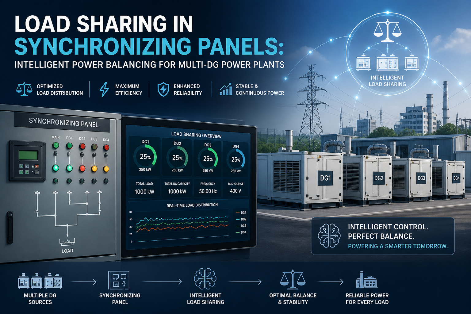
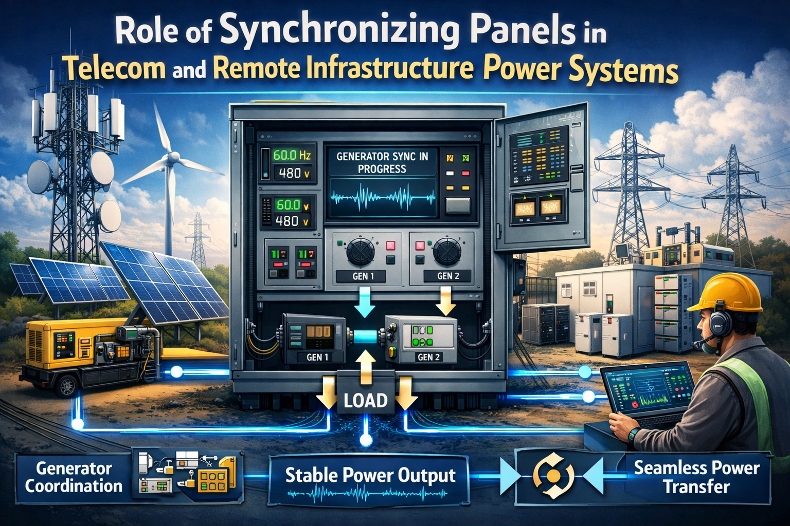
In commercial power systems where multiple generators operate together, synchronizing panels play a critical role in ensuring stable and safe power distribution. These panels synchronize generator parameters such as voltage, frequency, and phase angle before connecting them to a common busbar. For facilities that rely on generator-based backup or continuous power supply, selecting the right synchronizing panel becomes an important operational decision.

Businesses typically choose between manual synchronizing panels and automatic synchronizing panels depending on their power requirements, operational complexity, and automation needs. Understanding the differences between manual vs automatic synchronizing panels helps organizations select the most suitable solution for their electrical infrastructure.

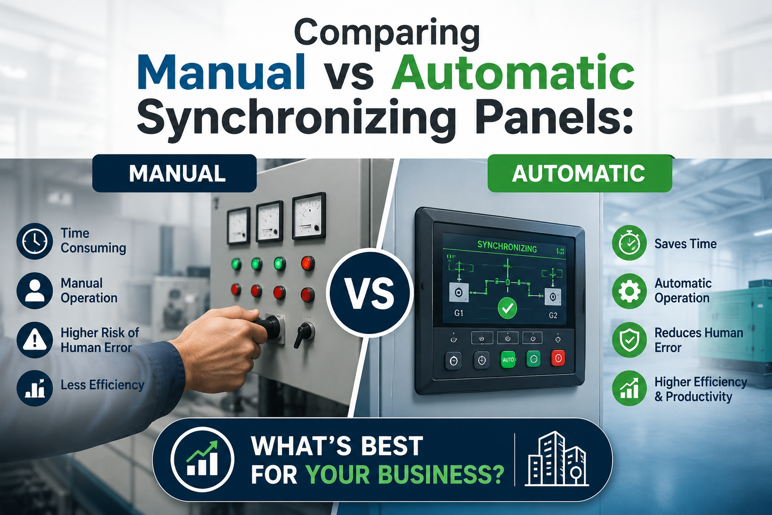
Manual Synchronizing Panels in Power Systems

A manual synchronizing panel requires an operator to monitor generator parameters and perform synchronization manually. The operator observes instruments such as voltmeters, frequency meters, and synchroscopes to ensure that the incoming generator matches the busbar conditions before closing the breaker.

Manual systems are often used in small commercial power systems where synchronization operations occur infrequently, and skilled operators are available to manage the process.

Because synchronization depends on human intervention, the process can take longer and requires careful monitoring. However, manual panels are generally simpler in design and involve lower initial investment compared to automated systems.

Automatic Synchronizing Panels for Modern Power Infrastructure

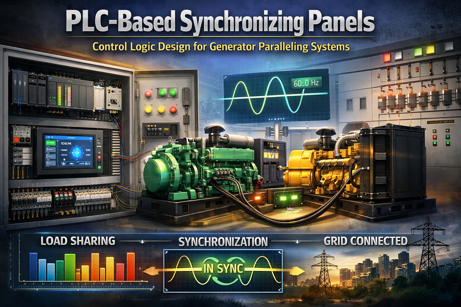
An automatic synchronizing panel uses advanced controllers and protection systems to perform generator synchronization automatically. These panels continuously monitor generator parameters and automatically adjust voltage, frequency, and load sharing before connecting generators to the electrical network.

In commercial facilities with multiple generators or critical power loads, automatic synchronization significantly improves operational efficiency. The system responds quickly to changing load conditions and can automatically start, synchronize, and share load among multiple generators.

Automation also reduces dependency on manual intervention and minimizes the risk of synchronization errors. This makes automatic synchronizing panels particularly valuable for data centers, hospitals, manufacturing facilities, and large commercial complexes where power continuity is essential.

Key Differences Between Manual and Automatic Synchronizing Panels

FeatureManual Synchronizing PanelAutomatic Synchronizing Panel
Operation MethodRequires operator to synchronize generators manuallySynchronization is handled automatically by control systems
Response TimeSlower due to manual monitoring and interventionFast synchronization with real-time controller adjustments
System ComplexitySimple design with basic instrumentsAdvanced controllers, PLCs, and protection relays
Human DependencyHigh dependency on trained operatorsMinimal human intervention required
Application SizeSuitable for small commercial power systemsIdeal for large commercial or industrial power systems
Load SharingOften manual or limitedAutomatic load sharing between generators

Choosing the Right Synchronizing Panel for Your Business

Selecting between a manual synchronizing panel and an automatic synchronizing panel depends largely on the scale and operational requirements of the power system.

Businesses operating smaller generator installations may find manual panels sufficient, particularly where synchronization operations occur rarely. However, as the complexity of the electrical network increases, automation becomes increasingly beneficial.

Modern commercial facilities often prefer automatic synchronizing panels because they provide faster generator response, improved load sharing control, and better integration with monitoring systems such as SCADA.

Manufacturers involved in electrical panel engineering, including Synchro Electricals, design synchronizing panels tailored to different power system requirements. Whether for manual or automated operations, well-designed panels help ensure safe generator synchronization and reliable power distribution.

FAQs

  1. 1. What is a synchronizing panel used for?

    A synchronizing panel ensures that multiple generators match voltage, frequency, and phase before connecting to a common electrical bus.

  2. 2. What is the main advantage of automatic synchronizing panels?

    Automatic panels synchronize generators faster and reduce the need for manual operator intervention.

  3. 3. Are manual synchronizing panels still used today?

    Yes, they are still used in smaller power systems where generator synchronization is performed occasionally.

  4. 4. Which industries use automatic synchronizing panels?

    Industries such as healthcare, data centers, manufacturing, and commercial complexes commonly use automatic synchronization systems.

  5. 5. Can synchronizing panels manage load sharing between generators?

    Yes, advanced automatic synchronizing panels can automatically balance electrical load between multiple generators.

SPD Selection and Earthing Coordination in ACDB/DCDB Panels for Solar Installations

Solar photovoltaic (PV) power plants operate in open environments where electrical systems are continuously exposed to lightning strikes, switching surges, and transient overvoltages. These events can cause severe damage to inverters, monitoring systems, and sensitive electrical components if adequate protection measures are not implemented.

In solar EPC projects, ACDB DCDB panels play a crucial role in managing power distribution between PV modules, inverters, and the grid. However, the reliability of these panels heavily depends on the correct implementation of surge protection in ACDB DCDB panels and proper earthing coordination.

Selecting the right Surge Protection Devices (SPDs) and integrating them with a well-designed grounding system ensures that transient overvoltages are safely diverted away from critical equipment. For large solar installations, proper SPD selection and earthing coordination in ACDB DCDB panels is therefore essential for long-term system stability and equipment protection.

Transient Overvoltages in Solar Power Systems

Solar plants are particularly vulnerable to electrical surges due to their extensive outdoor cable networks and elevated structures. Transient overvoltages may originate from multiple sources.

Lightning strikes are the most severe cause of surges in solar installations. Even indirect lightning strikes near a solar plant can induce high voltage spikes through electromagnetic coupling.

Other sources include switching operations within the power network, grid disturbances, and rapid changes in load conditions.

These surges propagate through DC cables, inverter terminals, and AC distribution systems. Without proper surge protection in ACDB DCDB panels, these voltage spikes can damage inverters, monitoring equipment, and control electronics.

Role of ACDB and DCDB Panels in Solar Electrical Architecture

In photovoltaic power systems, DCDB panels collect the DC output from multiple solar strings and route the combined power to the inverter. The inverter converts this DC power into AC power, which is then distributed through ACDB panels before being exported to the grid or connected loads.

Because both panels are part of the primary power path, they become critical points for installing surge protection devices.

SPDs installed in DCDB panels protect the inverter from voltage spikes originating on the DC side, while SPDs installed in ACDB panels protect the inverter and downstream equipment from grid-side surges.

Properly engineered ACDB DCDB panels for solar installations therefore integrate surge protection devices along with grounding systems to manage transient energy effectively.

Surge Protection Devices Used in ACDB DCDB Panels

Selecting the correct SPD type is a key aspect of surge protection design in solar installations. SPDs are categorized based on their surge handling capability and application environment.

Common SPD types used in solar ACDB and DCDB panels

Type 1 SPD

Type 1 SPDs are designed to handle direct lightning current impulses. They are typically installed at the main electrical service entrance where the building or plant is exposed to direct lightning strikes.

Type 2 SPD

Type 2 SPDs are the most commonly used protection devices in ACDB DCDB panels. These SPDs protect equipment from induced lightning surges and switching transients.

Type 1+2 Combined SPD

In large solar plants where lightning risk is significant, combined Type 1+2 SPDs are often installed to provide both lightning current protection and surge suppression in a single device.

Correct SPD selection depends on parameters such as maximum discharge current, nominal discharge current, system voltage, and short circuit withstand capability.

Critical Parameters for SPD Selection in Solar Panels

Selecting SPDs for ACDB DCDB panels in solar installations requires careful technical evaluation. Engineers must ensure that the SPD characteristics match the electrical properties of the PV system.

Important parameters considered during SPD selection for solar power systems include:

  • Maximum system voltage of the DC string or AC grid
  • Maximum discharge current rating (Imax)
  • Nominal discharge current (In)
  • Voltage protection level (Up)
  • Response time of the surge protection device

For DC circuits, SPDs must also be capable of handling continuous DC voltage without degradation. This is especially important in solar systems where DC voltage levels may exceed 1000V or even 1500V in utility-scale installations.

Earthing Coordination in ACDB DCDB Panels

While SPDs divert surge energy away from sensitive equipment, their effectiveness depends heavily on the earthing system of the solar plant. Without proper grounding, surge energy cannot be safely dissipated into the earth.

In solar installations, earthing coordination typically includes multiple grounding systems working together:

  • Equipment earthing for electrical safety
  • Lightning protection earthing for surge discharge
  • Functional earthing for stable system operation

The SPDs installed in ACDB DCDB panels must be connected to a low-impedance grounding network so that surge currents can flow quickly into the earth.

High earthing resistance can cause surge energy to remain within the system, increasing the risk of equipment failure.

Coordination Between SPD Placement and Grounding Layout

Effective surge protection in solar plants requires strategic placement of SPDs within the electrical network. Improper SPD placement can reduce protection effectiveness even if high-quality devices are used.

Typically, DCDB panels include SPDs installed between positive and negative conductors as well as between conductors and earth. This configuration ensures that surge currents are diverted regardless of the surge path.

Similarly, ACDB panels incorporate SPDs between phase conductors and earth, protecting the inverter and AC distribution network.

Short grounding conductors and proper bonding between earthing systems are essential to minimize impedance and allow efficient surge dissipation.

Impact of Improper Surge Protection on Solar Plants

Failure to implement proper SPD selection and earthing coordination in ACDB DCDB panels can lead to multiple operational problems in solar power plants.

Sensitive components such as inverters, monitoring equipment, and data loggers can be permanently damaged by voltage surges. Replacing these components often results in significant downtime and financial losses.

Additionally, repeated surge exposure can degrade insulation systems and reduce the lifespan of electrical equipment.

For solar EPC contractors and plant operators, proper surge protection in ACDB DCDB panels is therefore a critical design consideration that directly impacts plant reliability.

Synchro Electricals: Reliable ACDB DCDB Panels for Solar Projects

Synchro Electricals manufactures high-quality ACDB DCDB panels designed specifically for solar EPC projects and photovoltaic power plants. These panels are engineered to incorporate reliable surge protection systems and optimized earthing integration.

Each ACDB DCDB panel from Synchro Electricals is designed with proper SPD accommodation, robust enclosure construction, and electrical layouts that support safe surge energy dissipation.

With expertise in industrial electrical panels and solar power distribution systems, Synchro Electricals provides dependable panel solutions for solar installations operating in demanding environments.

Conclusion

Solar power plants operate in environments where electrical surges are unavoidable. Effective protection of critical equipment therefore, depends on proper SPD selection and earthing coordination in ACDB DCDB panels.

By integrating correctly rated surge protection devices with a well-designed grounding system, solar installations can safely manage transient overvoltages caused by lightning and switching events.

For EPC contractors and plant operators, investing in well-engineered ACDB DCDB panels with advanced surge protection systems is essential to ensure long-term reliability and uninterrupted solar power generation.

FAQs

  1. 1. Why are surge protection devices (SPDs) used in ACDB/DCDB panels for solar plants?

    SPDs protect solar inverters and electrical equipment from lightning surges and transient overvoltages by safely diverting surge energy to the earthing system.

  2. 2. What type of SPD is commonly used in ACDB and DCDB panels?

    Type 2 SPDs are commonly used for surge protection in ACDB/DCDB panels, while Type 1 or Type 1+2 SPDs may be used in areas with high lightning exposure.

  3. 3. Why is earthing coordination important for surge protection in solar installations?

    Proper earthing ensures that surge currents discharged by SPDs flow safely into the ground, preventing damage to inverters and other electrical components.

  4. 4. Where are SPDs installed in ACDB and DCDB panels?

    In DCDB panels, SPDs are installed between DC conductors and earth, while in ACDB panels, they are placed between phase conductors and earth to protect the inverter and AC distribution system.

  5. 5. What voltage levels must DC SPDs handle in solar systems?

    DC SPDs must be rated for the maximum PV system voltage, which can typically range from 600V to 1500V DC depending on the solar plant design.

Arc Quenching Characteristics of Vacuum Circuit Breakers in Medium Voltage Panels

Medium voltage power distribution systems demand switching devices that can interrupt fault currents quickly and reliably. In modern electrical infrastructure, vacuum circuit breakers (VCBs) installed in medium voltage panels have become the preferred solution for safe and efficient fault interruption. Their superior arc quenching technology allows them to extinguish electrical arcs rapidly while maintaining long operational life.

In industrial power networks, the ability to interrupt fault currents safely is critical. During switching or fault conditions, an electrical arc forms between separating contacts inside the breaker. If this arc is not extinguished immediately, it can cause severe equipment damage and compromise system stability. This is where VCB arc quenching technology offers significant advantages compared to traditional air or oil circuit breakers.

Why Arc Interruption Matters in Medium Voltage Power Distribution

In medium voltage panels, circuit breakers perform the essential task of protecting electrical systems from overloads and short circuits. When a fault occurs, the breaker contacts open to interrupt current flow. However, because current continues momentarily through ionized particles, an arc is formed between the separating contacts.

The ability to control and extinguish this arc determines the effectiveness of the circuit breaker. Poor arc control can lead to contact erosion, excessive heat generation, and even equipment failure.

Vacuum circuit breakers in VCB panels are specifically designed to handle these conditions. Their arc-quenching mechanism ensures that the arc is extinguished almost immediately, making them highly reliable for industrial power distribution systems.

The Physics Behind VCB Arc Quenching Technology

The core advantage of vacuum circuit breakers lies in the unique properties of the vacuum environment. Inside the vacuum interrupter, the pressure is extremely low—typically around 10⁻⁶ to 10⁻⁷ torr. This environment contains very few gas molecules, which significantly affects arc behavior.

When breaker contacts separate inside the vacuum interrupter, a metal vapor arc forms due to the evaporation of contact material. However, because there are almost no gas molecules to sustain ionization, the arc cannot persist for long.

As the current approaches its natural zero point in an AC waveform, the arc collapses rapidly. The vacuum environment quickly regains its insulating strength, preventing the arc from re-igniting. This process is the essence of VCB arc quenching technology.

The result is extremely fast arc interruption and minimal damage to breaker contacts.

Contact Design and Its Role in Arc Control

The effectiveness of arc quenching in vacuum circuit breakers is heavily influenced by the design of the breaker contacts. Specialized contact geometries are used to control the arc and distribute heat evenly across the contact surface.

Common contact designs used in VCB panels for medium voltage systems include:

  • Radial magnetic field contacts
  • Axial magnetic field contacts
  • Spiral slot contact structures

These designs create magnetic fields that force the arc to move across the contact surface rather than concentrating in a single spot. By distributing the arc energy, contact erosion is minimized and the breaker’s operational life is extended.

Advanced VCB arc quenching systems, therefore, combine vacuum insulation with carefully engineered contact designs to achieve efficient arc interruption.

Arc Behavior During Current Interruption

In a medium voltage vacuum circuit breaker, the arc exists only for a very short duration. As current flows through the arc, a plasma channel forms between the contacts. However, because the vacuum environment lacks sufficient ionized particles, the plasma rapidly dissipates.

The interruption process typically follows these stages:

  1. Contact separation initiates the arc formation.
  2. Metal vapor plasma forms between the contacts.
  3. Magnetic fields distribute the arc energy across the contact surface.
  4. Current reaches natural zero in the AC cycle.
  5. Arc collapses instantly due to vacuum insulation recovery.

This rapid arc extinction is what makes vacuum circuit breakers in medium voltage panels highly effective in modern electrical systems.

Performance Advantages of Vacuum Arc Quenching

The advanced arc quenching characteristics of VCB panels provide several important technical benefits in industrial power distribution systems.

Key technical advantages include:

Extremely Fast Arc Interruption
The arc is extinguished at the natural current zero, ensuring rapid fault clearing.

Minimal Contact Wear
The moving arc distributes heat across the contact surface, reducing erosion.

High Dielectric Recovery Strength
Vacuum insulation restores quickly after arc extinction, preventing restrikes.

Long Electrical and Mechanical Life
VCBs typically achieve tens of thousands of switching operations with minimal maintenance.

These characteristics make vacuum circuit breakers ideal for applications requiring reliable switching under demanding electrical conditions.

Why VCB Panels Are Preferred in Modern Medium Voltage Systems

Traditional oil circuit breakers and air circuit breakers once dominated medium voltage power distribution networks. However, these technologies required frequent maintenance and posed environmental risks.

Modern VCB panels equipped with vacuum circuit breakers offer a cleaner and more reliable alternative. Because arc quenching occurs in a sealed vacuum interrupter, there is no need for oil insulation or gas refilling.

As a result, VCB arc quenching technology has become the industry standard for medium voltage switchgear and power distribution panels used in industrial facilities, infrastructure projects, and utility networks.

Synchro Electricals: Engineering Reliable VCB Panels

Synchro Electricals manufactures advanced VCB panels designed for medium voltage power distribution systems. The company focuses on delivering robust switchgear solutions that incorporate high-performance vacuum circuit breaker technology.

Each VCB panel from Synchro Electricals is engineered with precision to ensure efficient arc interruption, reliable fault protection, and long operational life. These panels are widely used in industrial plants, infrastructure projects, and high-capacity power distribution networks.

By integrating proven VCB arc quenching technology with durable panel construction, Synchro Electricals provides dependable solutions for modern electrical systems.

Conclusion

In medium voltage electrical networks, safe and efficient fault interruption is essential for maintaining system stability. The arc quenching characteristics of vacuum circuit breakers make them one of the most reliable switching technologies used in VCB panels.

By utilizing vacuum insulation and advanced contact designs, VCB arc quenching technology allows circuit breakers to extinguish arcs quickly while minimizing wear and maintenance requirements.

For industries operating medium voltage power distribution systems, adopting VCB panels with advanced vacuum circuit breakers ensures greater reliability, improved safety, and long-term operational efficiency.

FAQs

  1. 1. What is arc quenching in a vacuum circuit breaker?

    Arc quenching in a vacuum circuit breaker refers to the rapid extinction of the electrical arc formed between separating contacts inside a vacuum interrupter during current interruption.

  2. 2. Why are vacuum circuit breakers used in medium voltage panels?

    Vacuum circuit breakers are preferred in medium voltage panels because they provide fast arc interruption, high dielectric strength, minimal maintenance, and long operational life.

  3. 3. How does a vacuum help in extinguishing the arc in VCBs?

    The vacuum environment contains very few gas molecules, so the arc cannot sustain ionization and quickly collapses when the current reaches its natural zero point.

  4. 4. What voltage range typically uses VCB panels?

    VCB panels are commonly used in medium voltage systems ranging from 3.3 kV to 36 kV in industrial power distribution and utility applications.

  5. 5. What are the advantages of VCB arc quenching technology?

    VCB arc quenching offers fast fault interruption, reduced contact wear, high insulation recovery, and reliable performance in medium voltage power distribution systems.

Load Sharing in Synchronizing Panels: Intelligent Power Balancing for Multi-DG Power Plants

Industrial facilities that rely on multi-DG power plants face a critical operational challenge – how to distribute electrical load efficiently across multiple generators. When several diesel generators operate together without proper coordination, the result can be unstable frequency, inefficient fuel usage, and uneven mechanical stress.

This is where automatic synchronizing panels play a vital role. Modern synchronizing panels integrate intelligent load sharing algorithms that automatically balance electrical demand among generators operating on the same busbar.

In large-scale power generation systems, proper load sharing in synchronizing panels ensures that each DG set contributes proportionally to the total power demand, improving efficiency and protecting expensive generator equipment.

Understanding the Load Sharing Challenge in Multi-DG Power Plants

Running a single diesel generator is relatively simple. However, when multiple generators operate simultaneously in industrial power plants, maintaining equilibrium becomes significantly more complex.

Each generator must match system parameters such as frequency, voltage, and phase angle before connecting to the power bus. Once connected, the generators must continuously adjust their output so that the electrical load is evenly distributed.

Without an effective load sharing mechanism in synchronizing panels, several operational problems can arise:

  • One DG set may become overloaded
  • Other generators may run underutilized
  • Fuel efficiency may drop significantly
  • Generator engines may experience premature wear

Advanced synchronizing panels used in power generation plants prevent these issues by implementing intelligent load distribution logic.

How Automatic Synchronizing Panels Manage Generator Coordination

A synchronizing panel acts as the control center of a multi-generator power system. It monitors electrical parameters from each generator and ensures that generators connect to the system safely.

Once synchronization is achieved, the panel’s control system manages generator output using specialized load sharing algorithms.

The panel continuously monitors parameters such as:

  • Generator real power output (kW)
  • System frequency and voltage
  • Generator engine speed
  • Power factor

Based on these readings, the automatic synchronizing panel dynamically adjusts generator performance to maintain balanced load distribution across all running DG sets.

Key Load Sharing Strategies Used in Modern Synchronizing Panels

Modern industrial synchronizing panels rely on several control methods to maintain stable generator operation. Each method is designed to ensure reliable load sharing in multi-DG power plants.

1. Droop-Based Load Sharing

The droop method is one of the most widely implemented techniques in automatic synchronizing panels. In this system, a generator’s frequency slightly decreases as its load increases.

Because every generator follows this behavior, the load naturally distributes across all DG sets connected to the bus. This method is commonly used in industrial power plants and manufacturing facilities due to its simplicity and reliability.

2. Isochronous Control for Precision Power Distribution

In facilities that demand extremely stable power – such as data centers or healthcare infrastructure – more precise control is required.

Isochronous control allows one generator to maintain system frequency while other generators share load proportionally. This approach ensures tight load regulation while maintaining stable electrical parameters across the entire system.

3. Digital Load Sharing Controllers

Modern synchronizing panels for power generation plants increasingly use microprocessor-based controllers that perform real-time load management.

These controllers communicate between generators and continuously adjust fuel injection and engine speed, ensuring optimal load balancing. Digital control systems improve both efficiency and system stability in large multi-generator installations.

Operational Advantages of Intelligent Load Sharing

Well-designed load sharing systems in synchronizing panels significantly improve generator plant performance. For industrial power facilities, these benefits directly translate into lower operating costs and improved system reliability.

Key operational advantages include:

Balanced Generator Utilization
All DG sets share electrical demand evenly, preventing overload conditions.

Improved Fuel Efficiency
Generators running at optimal load levels consume less fuel per unit of power generated.

Enhanced System Stability
Stable voltage and frequency are maintained even during sudden load changes.

Reduced Equipment Wear
Balanced load distribution minimizes mechanical stress on generator engines and alternators.

These advantages make automatic synchronizing panels with advanced load sharing algorithms essential for modern power generation systems.

Engineering Considerations for Synchronizing Panel Design

Designing synchronizing panels for multi-DG power plants requires advanced electrical engineering expertise. Panel design must ensure accurate measurement, reliable control, and strong protection mechanisms.

Critical components of a high-performance industrial synchronizing panel include:

  • Precision voltage and frequency sensors
  • Intelligent load sharing controllers
  • Programmable logic controllers (PLC)
  • Protection relays for reverse power and overload conditions
  • High-quality busbar systems

Together, these components enable reliable load sharing in synchronizing panels, ensuring smooth generator coordination in demanding industrial environments.

Synchro Electricals: Advanced Synchronizing Panel Solutions

Synchro Electricals is a trusted manufacturer of industrial synchronizing panels and generator control systems designed for reliable multi-DG power plant operations.

The company’s automatic synchronizing panels incorporate advanced control technologies and intelligent load sharing algorithms, ensuring stable generator coordination and efficient power distribution.

With deep expertise in industrial electrical panel manufacturing, Synchro Electricals delivers solutions that support power plants, infrastructure projects, manufacturing facilities, and critical power installations.

By combining engineering precision with robust panel design, Synchro Electricals helps industries maintain reliable and efficient generator synchronization and load management systems.

Final Thoughts

Operating multiple generators efficiently requires more than just connecting them to the same power bus. Proper coordination through synchronizing panels with advanced load sharing algorithms is essential for maintaining system stability and optimizing generator performance.

From droop-based control to digital load sharing systems, modern automatic synchronizing panels provide the intelligence needed to manage complex multi-DG power plants.

For industrial facilities that rely on dependable power generation, investing in high-quality synchronizing panels engineered for efficient load sharing ensures long-term operational reliability and energy efficiency.

FAQs

  1. 1. What is load – sharing in synchronizing panels?

    Load sharing in synchronizing panels ensures that multiple generators in a multi-DG power plant distribute electrical load evenly, preventing overload and improving overall power system efficiency.

  2. 2. Why are synchronizing panels important for multi-DG power plants?

    Synchronizing panels match voltage, frequency, and phase before connecting generators to the busbar, ensuring safe generator operation and stable power distribution.

  3. 3. Which load sharing method is commonly used in synchronizing panels?

    The droop control method is widely used in industrial synchronizing panels because it allows generators to naturally balance load without complex communication systems.

  4. 4. What industries use automatic synchronizing panels?

    Automatic synchronizing panels are commonly used in manufacturing plants, hospitals, data centers, power plants, and large infrastructure facilities where multiple generators operate together.

  5. 5. How do load-sharing algorithms improve generator performance?

    Advanced load-sharing algorithms optimize generator utilization, reduce fuel consumption, and maintain stable voltage and frequency in multi-generator power systems.

Weatherproof ACDB/DCDB Panels: Designing for Harsh Outdoor Industrial Environments

Outdoor electrical installations face challenges that indoor systems rarely encounter. Dust, moisture, extreme temperatures, and continuous exposure to environmental elements can severely affect electrical distribution systems. In such demanding conditions, weatherproof ACDB DCDB panels play a critical role in maintaining safe and reliable power distribution.

Industries such as solar power plants, infrastructure projects, telecom installations, water treatment facilities, and outdoor manufacturing units depend on durable ACDB DCDB panels designed specifically for harsh outdoor environments. A well-engineered weatherproof ACDB DCDB panel ensures protection against environmental damage while maintaining uninterrupted electrical performance.

For companies installing outdoor electrical infrastructure, selecting the right ACDB/DCDB panels for outdoor industrial installations is not just a technical decision—it is a long-term reliability investment.

Why Outdoor Industrial Installations Require Weatherproof ACDB/DCDB Panels

Unlike indoor electrical control systems, outdoor installations operate in unpredictable environments. Rain, humidity, dust storms, and fluctuating temperatures can compromise electrical components if proper protection is not in place.

Weatherproof ACDB DCDB panels are specifically designed to safeguard power distribution systems in such environments. These panels house critical components like MCBs, MCCBs, surge protection devices, and isolators, ensuring that solar arrays or power systems operate safely.

In solar plants, especially, ACDB panels distribute alternating current from inverters, while DCDB panels manage direct current from solar modules. If these panels are not properly protected, environmental exposure can lead to corrosion, short circuits, or system failures.

This is why modern outdoor ACDB DCDB panels incorporate specialized enclosures, sealing systems, and corrosion-resistant materials to maintain long-term performance.

Environmental Factors That Influence ACDB/DCDB Panel Design

Designing weatherproof ACDB DCDB panels requires careful consideration of environmental conditions. Each outdoor location presents different risks, which must be addressed through proper panel engineering.

Common environmental challenges include:

  • Heavy rainfall and humidity that may cause moisture intrusion
  • Dust and sand exposure in industrial zones or desert areas
  • Extreme heat and UV radiation affecting panel materials
  • Corrosion risks in coastal or chemical industrial areas
  • Temperature fluctuations causing expansion and condensation

A well-designed weatherproof electrical distribution panel protects internal components from these conditions while ensuring stable operation of the entire electrical system.

Key Design Features of Weatherproof ACDB/DCDB Panels

High-quality ACDB DCDB panels for outdoor industrial environments incorporate multiple protective features. These features are essential to ensure safety, durability, and efficient power distribution.

Important design elements include:

1. High IP Protection Rating

Outdoor ACDB/DCDB panels typically feature IP65 or IP66 protection, preventing dust and water ingress. This protection level ensures the panel remains operational even during heavy rain or dusty conditions.

2. Corrosion-Resistant Enclosures

Panels are often built using powder-coated CRCA steel or stainless steel enclosures. This prevents rust and corrosion in harsh industrial environments.

3. UV-Resistant Coatings

Continuous sun exposure can degrade conventional materials. UV-resistant coatings increase the lifespan of weatherproof ACDB DCDB panels used in solar installations.

4. Advanced Sealing and Gasketing

High-quality rubber gaskets prevent moisture from entering the enclosure, ensuring that sensitive electrical components remain protected.

5. Efficient Cable Management

Outdoor ACDB DCDB panels are designed with proper cable glands and entry points to maintain sealing integrity while allowing safe cable routing.

Where Weatherproof ACDB/DCDB Panels Are Commonly Used

Many industries depend on outdoor electrical distribution panels to manage power safely in exposed environments. These panels are especially critical in infrastructure where environmental exposure cannot be avoided.

Major industrial applications include:

  • Solar power plants and photovoltaic installations
  • Telecommunication towers
  • Water treatment and pumping stations
  • Outdoor manufacturing units
  • Infrastructure and construction projects

In solar power plants, DCDB panels collect power from solar modules, while ACDB panels distribute power from inverters to the grid. Weatherproof panel design ensures these operations remain stable regardless of environmental conditions.

Safety Considerations in Outdoor Electrical Panel Design

Electrical safety becomes even more important in outdoor installations. Exposure to moisture or dust can increase the risk of electrical faults if panels are not properly designed.

A reliable weatherproof ACDB DCDB panel must include protective features such as proper earthing systems, surge protection devices, circuit breakers, and insulated busbars. These safety mechanisms prevent electrical hazards while protecting connected equipment.

In solar installations, surge protection is particularly important, as lightning strikes or grid disturbances can cause significant damage to electrical systems.

Well-designed ACDB DCDB panels therefore, act as both distribution systems and safety barriers, protecting the entire electrical network.

Engineering Reliability for Long-Term Outdoor Performance

Outdoor electrical panels must perform reliably for years with minimal maintenance. This requires careful attention to material quality, ventilation design, and component selection.

Engineers must ensure that weatherproof ACDB DCDB panels maintain proper heat dissipation, as enclosed environments can trap heat. Ventilation systems, heat-resistant materials, and efficient layout designs help maintain optimal internal temperatures.

In large solar or infrastructure projects, the durability of ACDB DCDB panels directly affects system uptime and operational efficiency. Poorly designed panels may lead to frequent maintenance issues, affecting productivity and increasing operational costs.

Why Industries Trust Synchro Electricals for Weatherproof ACDB/DCDB Panels

Synchro Electricals has built a reputation for delivering high-performance industrial electrical panels designed for demanding environments. The company specializes in manufacturing weatherproof ACDB DCDB panels for outdoor industrial installations, ensuring reliable power distribution in challenging conditions.

Each ACDB/DCDB panel from Synchro Electricals is engineered with a focus on durability, safety, and long-term performance. From solar power projects to industrial infrastructure, the panels are designed to withstand harsh environmental exposure while maintaining electrical reliability.

With expertise in industrial electrical panel manufacturing and power distribution solutions, Synchro Electricals continues to support industries with dependable and technically advanced panel systems.

Conclusion

Outdoor electrical installations demand equipment that can withstand environmental stress while delivering consistent performance. Weatherproof ACDB DCDB panels provide the protection required to ensure safe and reliable power distribution in harsh industrial environments.

From solar plants to telecom infrastructure, these panels play a crucial role in safeguarding electrical systems against dust, moisture, and temperature extremes. By investing in high-quality weatherproof ACDB/DCDB panels, industries can ensure long-term operational stability and reduced maintenance challenges.

For businesses seeking robust ACDB DCDB panels for outdoor industrial installations, partnering with experienced manufacturers like Synchro Electricals ensures both reliability and performance in even the toughest environments.

FAQs

  1. 1. What is a weatherproof ACDB/DCDB panel?

    A weatherproof ACDB/DCDB panel is an outdoor electrical distribution panel designed to protect solar and industrial power systems from dust, rain, humidity, and harsh environmental conditions.

  2. 2. Where are ACDB and DCDB panels commonly used?

    ACDB/DCDB panels are widely used in solar power plants, telecom towers, water pumping stations, and outdoor industrial installations where safe power distribution is required.

  3. 3. What IP rating is recommended for outdoor ACDB/DCDB panels?

    Most outdoor installations require IP65 or IP66 rated ACDB/DCDB panels to ensure complete protection against dust ingress and heavy rain.

  4. 4. Why are weatherproof panels important for solar installations?

    Weatherproof ACDB/DCDB panels protect critical electrical components from environmental damage, ensuring stable power flow from solar modules to inverters and the grid.

  5. 5. What materials are used in weatherproof ACDB/DCDB panels?

    These panels are typically built with powder-coated CRCA steel or stainless steel enclosures along with sealed gaskets to prevent moisture and corrosion.

VCB Panels vs Traditional Breaker Panels: Safety & Performance Comparison in Industrial Power Distribution

Industrial power distribution systems operate under demanding electrical conditions. Manufacturing plants, processing industries, utilities, and heavy industrial facilities require switchgear solutions that can handle high fault levels, continuous operation, and strict safety standards. As electrical infrastructure evolves, many facilities are transitioning from traditional breaker panels to modern vacuum circuit breaker solutions.

When evaluating VCB panels vs conventional breakers, industrial engineers often focus on safety, reliability, and operational performance. Vacuum circuit breaker (VCB) panels are increasingly used in industrial power distribution networks, medium-voltage switchgear systems, and critical infrastructure facilities because they offer enhanced protection and faster fault interruption compared to older breaker technologies.

Understanding the differences between VCB panels vs conventional breakers helps plant operators and electrical engineers select the right switchgear for modern industrial environments.

How Industrial Switchgear Has Evolved

Traditional breaker panels were widely used in older industrial power distribution systems, particularly where electrical networks were smaller and fault levels were lower. These breaker panels relied on oil-based or air-based interruption mechanisms to clear electrical faults.

Modern industrial facilities, however, operate with larger transformers, heavy machinery, automation systems, and higher short-circuit levels. These changes have driven the adoption of vacuum circuit breaker panels in medium-voltage switchgear systems.

When comparing VCB panels vs conventional breakers, the main difference lies in how faults are interrupted. VCB panels use vacuum interrupters to extinguish arcs quickly and efficiently, which improves both safety and performance in industrial electrical networks.

Safety Considerations in Industrial Power Distribution

Safety is one of the primary reasons industries upgrade from traditional breaker panels to vacuum circuit breaker panels. Electrical faults in industrial power distribution systems can generate high arc energy, which poses serious risks to equipment and personnel.

VCB panels improve safety in several ways because the vacuum interrupter extinguishes arcs faster and contains the arc within a sealed environment. In comparison, conventional breaker panels may allow longer arc duration, increasing thermal stress on equipment.

When examining VCB panels vs conventional breakers, industrial engineers often highlight the following safety advantages of VCB technology:

  • Faster arc extinction in medium-voltage circuits
  • Reduced risk of arc flash in industrial switchgear systems
  • Improved operational safety for maintenance personnel
  • Better containment of fault energy inside switchgear panels

These features make VCB panels a preferred choice in modern industrial power distribution infrastructure.

Performance Differences in Industrial Electrical Systems

Performance is another key factor when comparing VCB panels vs conventional breakers. Industrial facilities require switchgear that can operate reliably under heavy electrical loads and frequent switching operations.

Traditional breaker panels may struggle in environments with frequent fault clearing or high switching cycles. VCB panels, on the other hand, are designed to handle repeated operations without significant wear.

In industrial medium-voltage distribution systems, VCB panels provide advantages such as improved switching reliability and reduced maintenance requirements. Because the arc is extinguished in vacuum, there is minimal contact erosion, which extends the service life of the breaker.

This improved durability makes VCB panels particularly valuable in industries with high operational demand.

Maintenance and Operational Efficiency

Maintenance is a major operational consideration in industrial facilities. Electrical switchgear that requires frequent servicing increases maintenance costs and production downtime.

In the comparison of VCB panels vs conventional breakers, vacuum circuit breaker panels typically require less maintenance because the interruption mechanism does not rely on oil or air insulation systems. Traditional breaker panels may require periodic oil replacement, contact maintenance, or cleaning to maintain reliable operation.

Industrial facilities, therefore, often favor VCB panels for their lower maintenance burden and longer operational lifespan.

Applications Across Industrial Power Distribution

Both types of breaker panels are used in industrial environments, but their applications vary depending on power system requirements.

Typical industrial environments where VCB panels are increasingly used include:

  • Medium-voltage distribution in manufacturing plants
  • Industrial substations and power distribution networks
  • Process industries such as steel, cement, and petrochemicals
  • Large motor control and heavy equipment power systems

These environments demand reliable protection systems capable of handling high electrical stress, which is why VCB panels are widely adopted.

Choosing Between VCB Panels and Conventional Breakers

Selecting between VCB panels vs conventional breakers depends on factors such as system voltage, fault levels, and long-term operational requirements. Older facilities with lower electrical demand may still operate effectively with traditional breaker panels, while modern industrial plants typically require the advanced protection capabilities of VCB switchgear.

As industrial power distribution systems become more complex, the need for faster fault clearing, higher safety standards, and improved reliability continues to increase.

Supporting Modern Industrial Power Infrastructure

Synchro Electricals develops vacuum circuit breaker panels designed for modern industrial power distribution environments. Their solutions support reliable fault interruption, improved operational safety, and long-term performance across manufacturing plants, processing industries, and infrastructure facilities.

Conclusion

The comparison of VCB panels vs conventional breakers highlights how industrial switchgear technology has evolved to meet the demands of modern power distribution systems. While traditional breaker panels served earlier industrial networks effectively, vacuum circuit breaker panels now offer improved safety, reliability, and operational efficiency.

For industries operating under heavy electrical loads and strict safety requirements, VCB panels provide a robust solution for protecting equipment and maintaining stable industrial power distribution.

FAQs

1. What is the main difference between VCB panels vs conventional breakers?

VCB panels use vacuum interrupters to extinguish arcs quickly, while conventional breakers typically rely on air or oil interruption methods.

2. Are VCB panels safer than traditional breaker panels?

Yes. Vacuum arc interruption reduces arc flash risk and improves safety in industrial switchgear systems.

3. Do VCB panels require less maintenance than conventional breakers?

Generally yes, because vacuum interrupters experience less contact wear and do not require oil handling.

4. Where are VCB panels commonly used in industry?

They are widely used in medium-voltage switchgear systems, industrial substations, and heavy manufacturing facilities.

5. Can existing plants upgrade from conventional breakers to VCB panels?

Yes. Many industrial facilities replace older breaker panels with VCB panels to improve reliability and safety.

PCC Panels for Textile Dyeing Units: Handling Heavy Load Fluctuations

Textile dyeing units are among the most power-sensitive environments in the textile and apparel industry. Dyeing machines, jet dyeing systems, drying units, pumps, compressors, and chemical processing equipment create continuous and fluctuating electrical loads. Managing this electrical demand requires a stable power distribution system, and that is where PCC Panels become essential.

In modern textile dyeing plants, PCC Panels for Textile Industry serve as the main electrical distribution backbone, ensuring stable power delivery, controlled load distribution, and safe operation across dyeing machines and textile processing equipment. Without properly designed textile dyeing units often face voltage instability, equipment shutdowns, and production delays.

Power Challenges Inside Textile Dyeing Units

Textile dyeing operations involve complex electrical loads that fluctuate throughout the production cycle. Dyeing machines, textile processing motors, water pumps, chemical dosing systems, and drying equipment frequently start and stop depending on production stages.

These load variations place significant stress on the plant’s electrical infrastructure. Textile factories require PCC Panels for the textile industry that can manage heavy load fluctuations while maintaining stable voltage and power distribution. When dyeing machines operate simultaneously, power demand can increase rapidly, making it reliable for maintaining consistent plant operations.

In textile processing plants, improper power distribution often leads to machine faults, uneven dyeing processes, and unexpected production interruptions.

Managing High Load Variations in Textile Dyeing Plants

Dyeing plants rarely operate under constant load conditions. During heating cycles, dyeing machines draw large amounts of power, while auxiliary systems such as circulation pumps and dryers create additional demand.

PCC Panels are designed to manage these heavy and variable loads by distributing power across different sections of the textile plant. By balancing electrical loads and preventing overload conditions, panels help textile dyeing units operate efficiently even during peak production hours.

Reliable power distribution allows dyeing machines, textile dryers, and processing equipment to run smoothly without electrical disturbances that could affect product quality.

Supporting Continuous Textile Production

Textile manufacturing facilities typically operate for long production shifts, often running machines continuously to meet production targets. Power interruptions during dyeing processes can lead to material waste, inconsistent dye quality, and significant production losses.

This is why PCC Panels for the Textile Industry are designed to support continuous plant operation. By maintaining controlled power flow and preventing electrical overloads, PCC Panels ensure an uninterrupted power supply to textile dyeing machines, processing equipment, and plant utilities.

Stable electrical infrastructure allows textile manufacturers to maintain production consistency and avoid costly downtime.

Coordinating Multiple Systems in Textile Processing Plants

Textile dyeing plants include multiple electrical systems operating together. Dyeing machines, air compressors, water treatment systems, effluent treatment plants, ventilation systems, and heating equipment all rely on coordinated power distribution.

They act as the central control point that manages these systems. By distributing power safely across the textile facility, PCC Panels for the Textile Industry help ensure that both production equipment and supporting infrastructure operate reliably.

Without properly engineered PCC panels, electrical imbalances can disrupt entire textile processing lines.

Power Stability for Quality Dyeing Operations

Consistent electrical supply is crucial for maintaining dyeing quality. Variations in voltage or power supply can affect heating elements, circulation pumps, and automated control systems used in textile dyeing.

PCC Panels for the Textile Industry help maintain power stability by regulating electrical distribution and protecting textile machines from overload or fault conditions. This stability ensures that dyeing processes remain consistent, helping textile manufacturers achieve uniform color quality across production batches.

Expanding Textile Manufacturing Capacity

Many textile manufacturers expand their dyeing capacity by adding new machines or increasing production lines. Electrical infrastructure must support this growth without requiring major redesign.

PCC Panels are typically designed with scalability in mind, allowing textile plants to add new dyeing machines, dryers, and auxiliary equipment as production demand increases. This flexibility makes PCC panels a long-term solution for growing textile facilities.

Reliable Power Infrastructure for Textile Plants

Synchro Electricals develops PCC Panels for the Textile Industry designed specifically for textile manufacturing environments, including dyeing plants, processing units, and textile production facilities. Their solutions help textile manufacturers manage high electrical loads while ensuring safe and efficient plant operations.

Conclusion

Textile dyeing units require reliable electrical systems capable of handling heavy and fluctuating power loads. PCC Panels for the Textile Industry provide the structured power distribution necessary to support dyeing machines, textile processing equipment, and plant utilities.

By stabilizing electrical supply, managing load variations, and supporting continuous production, PCC Panels for Textile Industry play a vital role in ensuring efficient and reliable operations across textile dyeing plants.

FAQs

1. Why are PCC Panels for Textile Industry important in textile dyeing units?

They manage high electrical loads from dyeing machines, pumps, dryers, and processing equipment, ensuring stable power distribution.

2. How do PCC Panels for the Textile Industry handle load fluctuations?

They distribute electrical loads across multiple feeders, preventing overload conditions during peak production.

3. Can PCC Panels for the Textile Industry reduce downtime in textile plants?

Yes. Reliable power distribution helps prevent machine shutdowns caused by electrical faults.

4. Are PCC Panels for the Textile Industry suitable for large textile factories?

Yes. They are designed to support heavy industrial loads and large-scale textile manufacturing operations.

5. Can PCC panels support expansion in textile dyeing plants?

Yes. PCC Panels for the Textile Industry are typically designed to allow additional machines and production lines to be integrated easily.

Role of Synchronizing Panels in Telecom and Remote Infrastructure Power Systems

Telecom networks operate in environments where uninterrupted power is not just desirable—it is mandatory. Telecom towers, remote telecom stations, and telecom data transmission hubs depend on reliable electrical infrastructure to maintain network connectivity 24/7. From rural telecom towers and mobile base stations to remote communication sites and fiber network hubs, power reliability directly determines service availability.

In these critical telecom environments, Synchronizing Panels for Telecom play a vital role in managing multiple power sources such as utility supply, diesel generators, and backup energy systems. Telecom power systems often operate in remote locations where grid supply may be unstable or unavailable. Synchronizing panels ensures that telecom infrastructure power systems can switch or operate between multiple sources without disruption.

Telecom Infrastructure Depends on Multi-Source Power Systems

Telecom networks rarely rely on a single power source. Most telecom towers and remote telecom infrastructure sites operate with a combination of grid power, diesel generator backup, and sometimes renewable energy systems such as solar hybrid telecom power solutions.

Managing these multiple sources requires careful coordination. Synchronizing Panels for Telecom enables telecom power systems to operate multiple generators in parallel, coordinate generator start-up, and maintain stable power for telecom equipment. Without proper synchronization, switching between power sources can cause voltage disturbances that may affect sensitive telecom electronics and communication hardware.

For telecom network operators, reliable synchronization is essential for ensuring uninterrupted connectivity.

Power Challenges in Remote Telecom Infrastructure

Remote telecom towers face unique electrical challenges. Many telecom sites are located in rural or hard-to-access areas where grid power reliability is limited. Frequent voltage fluctuations, unexpected outages, and inconsistent grid supply make backup power systems a necessity.

In these conditions, Synchronizing Panels for Telecom help telecom operators maintain stable operations by coordinating generator systems and managing load sharing between power sources. Telecom base stations often run critical equipment such as transmission radios, network routers, and cooling systems that cannot tolerate sudden power interruptions.

By enabling seamless transitions between generators and grid supply, synchronizing panels helps telecom infrastructure maintain operational continuity even during unstable power conditions.

How Synchronizing Panels Support Telecom Power Reliability

Telecom power systems must support continuous operation without manual intervention. When grid power fails, backup generators must start automatically and synchronize before taking over the telecom load.

Synchronizing Panels for Telecom manage this process by ensuring voltage, frequency, and phase alignment before connecting generators to the telecom power bus. This prevents electrical disturbances and protects sensitive telecom equipment.

In telecom tower infrastructure, synchronizing panels also enable multiple generators to operate in parallel. This allows telecom operators to distribute load efficiently across generator units, reducing fuel consumption and improving generator lifespan.

Reliable synchronization helps telecom operators maintain stable communication networks even in challenging operating environments.

Supporting Continuous Operation of Telecom Networks

Telecom infrastructure operates continuously, often without onsite operators. Automated power management, therefore, becomes essential. Synchronizing panels help telecom facilities run unattended by managing generator operation automatically.

With Synchronizing Panels for Telecom, telecom operators can maintain power continuity across:

  • Remote telecom towers
  • Cellular base stations
  • Telecom switching facilities
  • Fiber network hubs
  • Rural communication sites

These systems ensure telecom equipment receives stable power even when the grid supply is unavailable.

Ensuring Efficient Power Management in Telecom Sites

Energy efficiency is also a major concern for telecom operators. Running multiple generators inefficiently increases operational costs and maintenance requirements.

Synchronizing Panels for telecom improves efficiency by balancing loads across generators and preventing unnecessary generator operation. By optimizing generator usage, telecom infrastructure operators can reduce fuel consumption and extend equipment life.

Efficient power synchronization also supports hybrid telecom energy systems that combine solar power, battery storage, and diesel generators.

Scalability for Expanding Telecom Networks

Telecom networks continue to expand as demand for mobile connectivity, broadband services, and rural communication infrastructure increases. Power systems must be capable of supporting additional equipment and expanded network loads.

Synchronizing Panels for Telecom allows telecom operators to scale power infrastructure by integrating additional generators or energy sources without disrupting existing operations. This scalability is especially valuable for telecom providers expanding coverage in rural and remote regions.

Power Infrastructure Solutions for Telecom Environments

Synchro Electricals develops Synchronizing Panels for Telecom designed specifically for remote telecom infrastructure, telecom towers, and communication network facilities. Their synchronizing solutions support reliable power coordination, stable generator operation, and uninterrupted telecom network performance.

Conclusion

Telecom networks depend on reliable power infrastructure to maintain continuous communication services. In remote telecom sites and distributed telecom networks, managing multiple power sources effectively is essential.

Synchronizing Panels for telecom ensures seamless coordination between grid supply, generators, and backup systems, enabling telecom operators to maintain uninterrupted service even in challenging power environments. As telecom infrastructure continues to expand, synchronizing panels remains a key component of reliable telecom power systems.

FAQs

1. Why are Synchronizing Panels for Telecom important in telecom towers?

They coordinate multiple power sources, such as generators and grid supply, to ensure continuous power for telecom equipment.

2. How do Synchronizing Panels for Telecom improve telecom network reliability?

They allow seamless switching and parallel operation of generators, preventing power interruptions in telecom infrastructure.

3. Can synchronizing panels support remote telecom sites without operators?

Yes. Synchronizing Panels for Telecom enable automated power management in unattended telecom stations.

4. Do telecom power systems require multiple generators?

Many telecom towers and communication sites use multiple generators for redundancy, which are managed through synchronizing panels.

5. Can Synchronizing Panels for Telecom support hybrid energy systems?

Yes. They can coordinate generators with renewable energy sources such as solar systems used in telecom infrastructure.

PLC-Based Synchronizing Panels: Control Logic Design for Generator Paralleling Systems

In industrial power systems, generator paralleling is no longer a niche requirement limited to large power plants. Manufacturing facilities, process industries, data centers, and critical infrastructure increasingly rely on multiple generators operating in parallel with each other and with the utility grid. In these environments, the reliability of synchronization is defined not by hardware alone, but by the intelligence of the control system behind it.

This is where a PLC – Based Synchronizing Panel becomes central. Unlike conventional relay-based systems, PLC-driven synchronizing panels offer deterministic logic execution, advanced sequencing capability, and full adaptability to complex operating scenarios. For engineers, the real value lies in how the control logic is designed, validated, and coordinated with generator dynamics.

Why PLC-Based Synchronizing Panels Are Preferred in Industrial Power Systems

Traditional synchronizing relays are effective for basic voltage, frequency, and phase matching, but they are inherently limited in flexibility. Industrial power systems often require conditional logic, multi-mode operation, and interaction with auxiliary systems such as fuel management, load shedding, and process interlocks.

A PLC Based Synchronizing Panel allows synchronization to be treated as a control problem rather than a discrete event. The PLC continuously evaluates system states, generator availability, breaker status, and grid conditions before executing synchronization decisions. This capability is essential when paralleling multiple generators with varying ratings, response characteristics, and operating priorities.

Control Architecture of a PLC-Based Synchronizing Panel

At the core of a PLC-based system is a real-time control loop that monitors electrical parameters and system status. Voltage, frequency, and phase angle are acquired through transducers or digital meters, while breaker status, generator readiness, and fault signals are processed as discrete inputs.

The PLC executes synchronization logic cyclically, ensuring that decisions are based on current system conditions rather than static thresholds. This architecture enables coordinated control across generators, grid incomers, and bus couplers within a single control platform.

Crucially, the PLC does not replace protective relays; instead, it coordinates with them. Protection remains autonomous and fast, while the PLC manages sequencing, permissive logic, and operational control.

Synchronization Logic Design Using PLC

PLC-Based Synchronizing Panel – Pre-Synchronization Logic

Before synchronization, the PLC verifies that the generator is electrically and mechanically ready. This includes confirmation of rated voltage buildup, stable frequency, correct phase rotation, and acceptable governor and AVR response.

Speed and voltage ramping are controlled gradually to avoid overshoot. Unlike relay-based systems that wait passively for alignment, PLC logic actively drives the generator toward synchronism using feedback control. This reduces synchronization time while minimizing transient stress.

PLC-Based Synchronizing Panel – Breaker Closing and Validation Logic

Once synchronization criteria are met within defined tolerances, the PLC issues a breaker close command. However, advanced PLC logic also validates post-closure conditions. It checks for successful breaker operation, confirms that slip frequency collapses as expected, and ensures that no abnormal current or power flow is detected.

If post-synchronization conditions deviate from expected behavior, the PLC can initiate corrective action or controlled disconnection, preventing unstable operation from propagating into the system.

Load Sharing and Post-Synchronization Control

Synchronization is only the first step. In generator paralleling systems, stability depends heavily on how load is shared after connection. PLC-based panels integrate load-sharing algorithms that coordinate governor and AVR references to distribute active and reactive power proportionally.

The PLC continuously monitors real power, reactive power, and frequency deviation to damp oscillations and prevent hunting between generators. This is particularly important in industrial systems with fluctuating loads or large motor starts, where poor load sharing can lead to instability or nuisance tripping.

Handling Multiple Operating Modes

One of the strongest advantages of a PLC Based Synchronizing Panel is its ability to manage multiple operating modes within the same logic framework. These may include island mode operation, grid-parallel operation, generator-only mode, or black-start scenarios.

Each mode requires different synchronization permissives, sequencing rules, and protection coordination. PLC logic enables these modes to coexist without hardware modification, allowing operators to transition between configurations safely and predictably.

Failure Handling and Logic Robustness

In real-world systems, synchronization does not always succeed on the first attempt. Voltage instability, governor lag, or grid disturbances can interrupt the process. PLC-based logic handles these scenarios deterministically by aborting synchronization sequences, resetting conditions, and retrying only when stability is restored.

This approach avoids repeated mechanical stress and uncontrolled breaker operations, which are common failure modes in poorly designed systems.

Engineering Approach of Synchro Electricals

Synchro Electricals designs PLC-based synchronizing panels with a control-engineering-first philosophy. Synchronization logic is developed as a structured sequence with clearly defined states, transitions, and failure responses. Generator dynamics, grid behavior, and operational requirements are modeled into the PLC logic rather than handled as afterthoughts.

This approach ensures that the PLC-based synchronizing panel performs reliably under complex industrial conditions, including multi-generator operation, weak grids, and variable load profiles.

Conclusion

In modern industrial power systems, synchronization is no longer a single moment of alignment but a continuous control function. A PLC-based synchronizing panel provides the intelligence, flexibility, and determinism required to manage generator paralleling safely and efficiently.

By focusing on robust control logic design—covering pre-synchronization, breaker control, load sharing, and failure handling—engineers can build systems that remain stable under real operating stress. PLC-based synchronization is not simply an upgrade in technology; it is a fundamental shift toward system-level power control.

FAQs

1. What differentiates a PLC Based Synchronizing Panel from relay-based systems?

A PLC Based Synchronizing Panel uses deterministic control logic to manage synchronization, sequencing, and load sharing, whereas relay-based systems are limited to threshold-based matching of voltage, frequency, and phase.

2. Can a PLC Based Synchronizing Panel handle multiple generators with different ratings?

Yes. PLC logic can be customized to account for generator capacity, response characteristics, and priority, enabling stable paralleling of unequal machines.

3. How does PLC logic improve synchronization reliability?

PLC logic actively controls speed and voltage ramping, validates post-breaker conditions, and aborts unsafe sequences, reducing transient stress and synchronization failures.

4. Is PLC-based synchronization dependent on protection relays?

Protection relays operate independently for fault clearing. The PLC coordinates operational logic but does not replace protection functions.

5. Can PLC Based Synchronizing Panels support island and grid-parallel operation?

Yes. Multiple operating modes can be implemented within the same PLC program, allowing seamless transitions between islanded and grid-connected states.

Protection Relay Integration and Interlocking Logic in VCB Panels for MV Switchgear

In utility and substation environments, medium-voltage (MV) switchgear is expected to operate under high fault levels, dynamic grid conditions, and strict reliability requirements. At the center of this infrastructure, VCB panels serve as both the switching and protection interface between the grid and downstream networks. However, the true effectiveness of a VCB panel is determined not by the breaker alone, but by the robustness of its VCB Panel Protection Relay Scheme.

Modern substations rely on numerical protection relays, intelligent control logic, and fail-safe interlocking philosophies to ensure that faults are detected, isolated, and cleared without compromising system stability or personnel safety. Protection relay integration and interlocking logic, therefore form the backbone of MV switchgear design.

Role of Protection Relay Integration in VCB Panels

Protection relay integration in VCB panels involves coordinating multiple protection functions—overcurrent, earth fault, feeder protection, breaker failure protection, and inter-tripping—within a unified control and protection architecture. In utility-grade MV switchgear, this integration must align with overall substation protection philosophy and grid code requirements.

Numerical protection relays for VCB panels continuously monitor current, voltage, and status inputs, converting raw electrical quantities into protection decisions. These relays must interface seamlessly with trip circuits, breaker mechanisms, and control relays, ensuring deterministic operation during fault conditions. Poor relay integration can result in delayed tripping, unwanted breaker operation, or complete failure to clear faults.

VCB Panel Protection Relay Scheme Architecture

A typical VCB panel protection relay scheme is structured around functional separation. Protection relays handle fault detection and tripping logic, while control circuits manage breaker operation, indication, and SCADA interfacing. This separation ensures that protection functions remain operational even if control or communication systems fail.

In 11kV and 33kV applications, feeder protection relay schemes are commonly implemented using numerical relays with configurable settings and communication capability. These relays coordinate with upstream and downstream devices to maintain selectivity, while also supporting redundancy where required by utility standards.

Integration increasingly includes IEC 61850 communication, allowing protection relays to exchange signals through GOOSE messaging rather than hardwired interconnections. While this improves speed and flexibility, it also places higher demands on interlocking logic design.

Interlocking Logic Design in VCB Panels

Interlocking logic is the mechanism that prevents unsafe operations within MV switchgear. In VCB panels, interlocking exists at multiple levels—mechanical, electrical, and logical.

Electrical and logical interlocking ensure that breaker closing is permitted only when predefined conditions are satisfied. These conditions may include correct isolator position, absence of earth switch engagement, healthy trip circuit supervision, and valid protection relay status. Logical interlocking implemented within numerical relays or control relays adds an additional layer of safety by enforcing operational sequences.

In substation environments, interlocking logic design must consider normal operation, maintenance conditions, and abnormal scenarios such as breaker failure or protection malfunctions. A poorly defined interlock can be as dangerous as no interlock at all.

Protection Relay Coordination and Interlocking Interaction

Protection relay coordination and interlocking logic are closely linked. For example, breaker failure protection relies on both relay logic and interlocking to initiate upstream tripping when a breaker fails to clear a fault. Similarly, inter-trip and blocking schemes require precise coordination between relays across multiple VCB panels.

In MV switchgear protection design, the interlocking philosophy must support fast fault clearance without allowing incorrect or premature breaker operation. This is particularly important in busbar and feeder interlocking logic, where incorrect coordination can lead to bus outages or equipment damage.

Fail-Safe Philosophy in Utility-Grade MV Switchgear

Utility and substation applications demand a fail-safe approach to protection and control. The VCB panel protection and control philosophy must ensure that any failure—loss of auxiliary supply, relay malfunction, communication failure—results in a safe system state.

This is achieved through redundancy in protection relay schemes, supervised trip circuits, and permissive logic that defaults to blocking unsafe operations. Control relay vs protection relay coordination is critical here; protection must always take precedence over control commands.

SCADA and Communication Integration

Modern substations require seamless SCADA integration with protection relays for monitoring, event analysis, and remote operation. However, SCADA must remain supervisory in nature. Protection decisions within the VCB panel protection relay scheme must remain local and autonomous to avoid dependency on external systems.

IEC 61850-based architectures enhance visibility and coordination but must be implemented with strict cybersecurity and reliability considerations, especially in grid-connected MV protection systems.

Engineering Perspective of Synchro Electricals

Synchro Electricals designs VCB panels with a protection-first philosophy. Relay integration, interlocking logic, and fail-safe design are treated as core engineering disciplines rather than wiring exercises. Each VCB panel protection relay scheme is developed in alignment with utility protection standards, substation operating practices, and real-world fault behavior.

Conclusion

In utilities and substations, MV switchgear reliability is defined by the quality of its protection and interlocking design. A well-engineered VCB Panel Protection Relay Scheme ensures that faults are cleared selectively, unsafe operations are prevented, and system stability is preserved under all operating conditions.

Protection relay integration and interlocking logic are not independent elements—they function as a unified system. When designed correctly, they transform VCB panels into intelligent, fail-safe components of modern power transmission infrastructure.

FAQs

1. What is a protection relay in VCB panels?

<p

2. Why is relay integration important in MV switchgear?

Relay integration ensures accurate fault detection, faster response time, and coordinated protection across the entire medium voltage system.

3. What is interlocking logic in VCB panels?

Interlocking logic is a safety mechanism that prevents incorrect operations, such as closing a breaker under unsafe conditions or opening during load transfer.

4. How does interlocking improve safety in switchgear systems?

It prevents human errors and ensures that operations follow a safe sequence, reducing the risk of equipment damage and electrical hazards.

5. What types of protection relays are used in MV switchgear?

Common relays include overcurrent relays, earth fault relays, differential relays, distance relays, and numerical relays.

Welcome to Synchro Electricals

We provide trusted, high-performance electrical solutions tailored for every industry.

Apply For Job