ACDB & DCDB Panels in EV Charging Stations: Ensuring Safe & Efficient Power Delivery

EV charging stations are no longer experimental infrastructure. They are now permanent, high-load electrical installations operating in public spaces, commercial premises, highways, and fleet depots. As charging capacities increase and fast chargers become standard, the electrical backbone behind these stations must handle continuous demand, thermal stress, and strict safety requirements.

In this environment, ACDB DCDB panels for EV charging are not secondary components. They define how power enters the site, how it is controlled, and how safely it reaches every charging point. Poorly designed distribution panels lead to frequent trips, overheating, inefficient energy use, and operational downtime—issues that directly affect charger availability and user trust.

How Power Distribution Shapes EV Charging Performance

Every EV charging station operates with a mix of AC and DC power. Incoming grid supply is managed on the AC side, while fast chargers rely heavily on DC distribution after conversion. This dual nature makes power management in EV charging stations fundamentally different from conventional electrical installations.

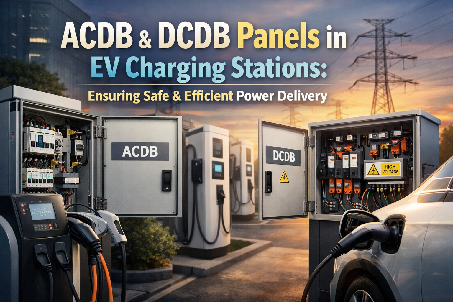
ACDB DCDB panels for EV charging provide the structured separation and coordination required to manage this mixed power environment. ACDB panels regulate and protect incoming AC supply, while DCDB panels handle high-current DC distribution to chargers. When these panels are designed as part of a single system rather than isolated units, power delivery becomes predictable, efficient, and safe.

Challenges Unique to EV Charging Stations

EV charging stations face electrical challenges that typical commercial buildings do not. Chargers operate for long durations at high current levels, often simultaneously. Fast-charging hubs experience rapid load fluctuations as vehicles connect and disconnect. Outdoor installations add environmental stress such as heat, dust, and moisture.

Without dedicated ACDB DCDB panels for EV charging, these conditions lead to uneven load distribution, frequent protective trips, and accelerated component wear. Distribution panels must be designed to support continuous operation while maintaining thermal stability and electrical safety.

ACDB & DCDB Panels as the Control Layer of EV Infrastructure

Rather than viewing ACDB and DCDB panels as simple distribution points, EV infrastructure treats them as control layers. These panels determine how power is prioritized, isolated, and expanded as charging demand grows.

ACDB panels ensure stable power flow from the grid to chargers and auxiliary systems such as lighting, monitoring, and payment terminals. DCDB panels manage DC outputs with precise isolation, ensuring that a fault in one charging line does not disrupt the entire station. Together, ACDB DCDB panels for EV charging enable selective operation, allowing stations to remain partially active even during faults or maintenance.

Impact on Safety, Reliability, and User Experience

For EV charging operators, safety and uptime directly influence reputation and revenue. Public charging stations must operate safely under all conditions while remaining accessible to users at all hours.

Well-engineered ACDB DCDB panels for EV charging reduce risks associated with electrical faults, overheating, and uncontrolled energy flow. They also improve reliability by ensuring consistent voltage and current delivery, which directly affects charging speed and equipment lifespan. From the user’s perspective, this translates into dependable charging sessions and minimal downtime.

Supporting Scalable EV Charging Networks

EV infrastructure is expanding rapidly. Charging stations installed today are often expected to support additional chargers, higher power ratings, or new charging technologies in the future. Power distribution systems must be designed with this scalability in mind.

ACDB DCDB panels for EV charging allow structured expansion by providing spare feeders, modular layouts, and clear separation between AC and DC systems. This approach enables operators to upgrade charging capacity without redesigning the entire electrical system, saving time and capital costs.

Design Considerations for Modern EV Charging Stations

Effective ACDB and DCDB panels are designed around real operating conditions rather than theoretical loads. Thermal management, fault isolation, and accessibility for maintenance are key factors. Panels must support frequent switching operations and continuous current flow without degradation.

In EV charging environments, panel reliability is just as important as charger technology itself. Distribution failures often result in multiple chargers going offline simultaneously, amplifying operational losses.

Delivering Infrastructure-Grade Power Distribution for EV Charging

Synchro Electricals develops ACDB DCDB panels for EV charging with a clear focus on infrastructure reliability and long-term performance. Designs are aligned with real-world EV charging conditions, ensuring safe power delivery, efficient operation, and readiness for future expansion.

Conclusion

EV charging stations depend on more than chargers alone. Behind every reliable charging point is a power distribution system capable of handling continuous demand, mixed AC/DC operation, and strict safety expectations.

By investing in well-designed ACDB DCDB panels for EV charging, operators create infrastructure that is safe, scalable, and ready for the next phase of electric mobility. In a rapidly evolving EV ecosystem, robust power distribution is not just supportive—it is foundational.

FAQs

1. Why are ACDB DCDB panels important in EV charging stations?

EV charging stations operate with both AC and DC power at high load levels. ACDB DCDB panels for EV charging ensure controlled distribution, protection, and isolation across the entire power system.

2. How do ACDB and DCDB panels improve charging station reliability?

They manage load distribution, handle continuous current demand, and isolate faults selectively, preventing a single issue from shutting down the entire station.

3. Are standard electrical panels suitable for EV charging infrastructure?

No. EV charging stations require panels designed for high current, frequent switching, and mixed AC/DC operation, which standard panels are not built to handle.

4. Do ACDB DCDB panels support fast and ultra-fast chargers?

Yes. Properly designed ACDB DCDB panels for EV charging support high-power DC fast chargers by managing DC distribution safely and efficiently.

5. Can EV charging stations be expanded without redesigning the entire system?

Yes. ACDB and DCDB panels are typically designed with modular feeders and capacity margins, allowing future expansion with minimal disruption.

Selective Coordination and Protection Scheme Design in PCC Panels for Industrial Facilities

In modern manufacturing plants, electrical power systems operate under high fault levels, dense load concentration, and increasingly complex operating modes. As automation, large motor drives, and redundant supply arrangements become standard, the role of the Power Control Center (PCC) panel extends far beyond power distribution. It becomes the primary decision point for fault isolation, system stability, and personnel safety. Within this context, selective coordination is not an optional design enhancement—it is a fundamental requirement.

For technical professionals, understanding PCC Panel Protection Coordination begins with recognizing how faults behave in industrial power systems and how protection decisions propagate through the electrical network.

Fault Behavior in Industrial Power Distribution Systems

When a fault occurs within a manufacturing facility, fault current does not remain localized by default. It flows upstream through multiple protective devices, each capable of detecting the same abnormal condition. In an uncoordinated system, several breakers may respond simultaneously, causing widespread loss of supply even when the fault is limited to a single feeder.

At the PCC level, fault current magnitudes are typically at their highest due to proximity to transformers or utility incomers. This makes protection decisions at this point especially critical. A poorly coordinated response can result in upstream breaker operation, disconnecting entire production areas instead of isolating only the affected circuit.

Selective coordination exists to control this behavior intentionally.

Selective Coordination Defined at the PCC Level

Selective coordination is the deliberate arrangement of protective device characteristics so that, for any given fault, only the device closest to the fault operates while upstream devices remain closed. At the PCC panel, this coordination must extend across incomers, bus couplers, and outgoing feeders.

Unlike theoretical textbook systems, real manufacturing plants contain motors with high inrush currents, drives that distort current waveforms, and operating modes that alter available fault current. Protection coordination must therefore be dynamic in concept, even if implemented through static settings.

At its core, selective coordination is achieved by carefully managing time–current relationships between devices while ensuring fault clearing remains fast enough to protect equipment and personnel.

Why Coordination Becomes Complex in Manufacturing Facilities

Manufacturing plants introduce coordination challenges that are rarely present in simpler installations. Large induction motors demand protection that tolerates starting currents without nuisance tripping. Variable frequency drives introduce harmonics that influence sensing accuracy. Parallel feeders and redundant supplies alter fault current paths, making intuitive coordination unreliable.

Additionally, many plants operate with multiple power sources, such as grid supply supplemented by DG sets. Fault levels change significantly between operating modes, meaning coordination that works under grid supply may fail under generator operation if not designed holistically.

These realities make default breaker settings inadequate for industrial PCC panels.

Protection Scheme Design Philosophy in PCC Panels

Effective PCC Panel Protection Coordination begins with system-level thinking. The PCC panel is not designed in isolation; it must be coordinated with upstream utility protection and downstream MCCs and distribution boards.

Design starts with accurate short-circuit analysis under all operating conditions. From this, protective device ratings and interrupting capacities are selected. Coordination studies then align long-time, short-time, instantaneous, and earth-fault elements so discrimination is preserved across the fault current spectrum.

Electronic trip units and digital relays are essential in this process. Their adjustable characteristics allow fine-tuning of response times, enabling engineers to balance speed and selectivity rather than sacrificing one for the other.

Achieving Practical Protection Coordination

In practice, coordination is an iterative engineering process rather than a one-time calculation. Time–current curves are analyzed to verify separation between downstream and upstream devices. Settings are validated against motor starting conditions and transient load behavior. Coordination is then rechecked under alternate supply scenarios, such as DG operation or transformer outages.

The PCC panel must also account for mechanical interlocking and operational logic. Bus coupler behavior, incomer transfer schemes, and maintenance modes all influence protection response and must be considered during design.

Coordination that exists only on paper but fails under real operating conditions offers no practical value.

Advanced Coordination Techniques in Critical Plants

In high-reliability manufacturing environments, traditional time grading alone may not provide acceptable fault clearance times. Advanced techniques such as zone-selective interlocking allow downstream devices to trip instantaneously while upstream devices restrain, achieving both speed and selectivity.

Logic-based protection schemes further enhance coordination by adapting responses based on system configuration. These approaches are particularly valuable where fault energy reduction and arc-flash mitigation are design priorities.

Safety, Reliability, and Compliance Implications

Poor coordination increases arc-flash incident energy by delaying fault clearing at high current levels. Properly coordinated PCC panels reduce this risk while maintaining operational continuity. From a compliance perspective, insurers and safety auditors increasingly expect documented coordination studies as part of industrial electrical design.

For plant operators, the benefit is tangible: faults are isolated quickly, downtime is contained, and electrical assets experience less stress over their service life.

Engineering Perspective of Synchro Electricals

Synchro Electricals approaches PCC panel design as a protection engineering discipline rather than an assembly exercise. Coordination studies, operating mode analysis, and application-specific protection logic form the foundation of every PCC solution. This ensures that protection performance in the field matches design intent, even under complex industrial conditions.

Conclusion

Selective coordination is the difference between controlled fault isolation and widespread production disruption. In manufacturing plants, where electrical complexity and uptime requirements continue to rise, PCC Panel Protection Coordination must be treated as a core design responsibility.

By applying rigorous protection scheme design at the PCC level, industrial facilities can achieve safer operation, higher reliability, and predictable system behavior under fault conditions. Coordination is not a setting—it is an engineered outcome.

FAQs

1. What is selective coordination in a PCC panel?

Selective coordination is the intentional grading of protective devices so that only the breaker nearest to a fault operates, while upstream devices remain closed.

2. Why is selective coordination critical in manufacturing plants?

Manufacturing facilities have high fault levels and sensitive production loads; poor coordination can cause plant-wide shutdowns from localized faults.

3. Can thermal-magnetic breakers achieve proper coordination?

In most industrial systems, no. Adjustable electronic trip units or digital relays are required to manage complex fault and load conditions accurately.

4. Does protection coordination change during DG operation?

Yes. DG operation alters fault current levels and direction, requiring coordination to be validated under both grid and generator modes.

5. How does protection coordination affect arc-flash safety?

Proper coordination reduces fault clearing time at higher current levels, directly lowering arc-flash incident energy and improving personnel safety.


Welcome to Synchro Electricals

We provide trusted, high-performance electrical solutions tailored for every industry.

Apply For Job