Every switchgear failure we’ve been called in to investigate over the years traces back to the same root cause: someone selected a breaker, an ACB, or a busbar system based on the load current the panel would carry — not the fault current it would have to survive. Load current tells you what the panel does on a normal Tuesday. Fault-level calculation tells you what the panel has to survive on its worst day, and that single number is what actually decides which switchgear belongs inside it.
At Synchro Electricals, we design and build LT and HT panels — PCC panels, MCC panels, VFD panels, APFC panels, and solar ACDB/DCDB boxes — for industrial plants, EPC contractors, and solar developers across India. In this guide, we’re breaking down exactly how fault-level calculation drives switchgear selection, in the same terms we use on our own engineering drawings.
What “Fault Level” Actually Means
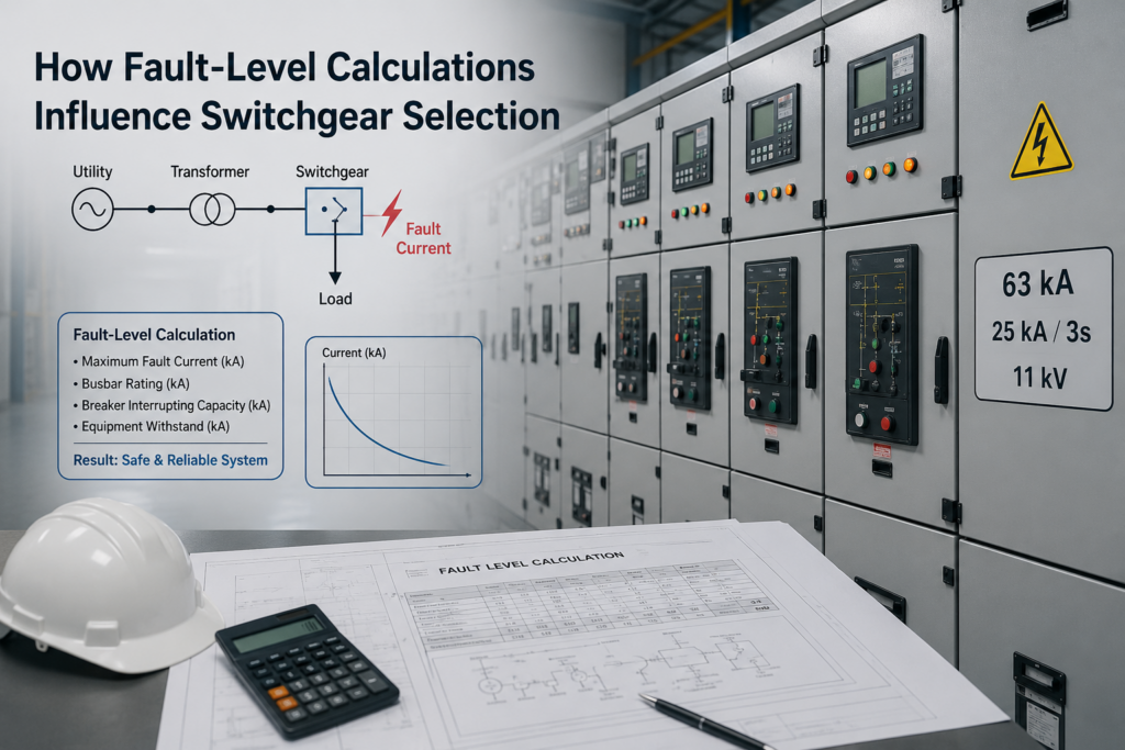
Fault level (also called short-circuit level or short-circuit MVA) is the maximum current a network can deliver into a bolted three-phase fault at a specific point in the system — an incomer, a busbar section, or a feeder. It isn’t a fixed property of the switchgear; it’s a property of the network at that point, shaped by the utility source, transformer impedance, cable/bus-duct impedance, and any motor or generator contribution nearby.
This is why the same MCC panel design can need a 35 kA breaker in one plant and a 65 kA breaker in another — the panel doesn’t decide the fault level; the source impedance feeding it does.
Why Fault Level Comes First, Not Last
A surprising number of specification sheets still list switchgear by current rating (A) and voltage (V) without confirming the fault level at the point of installation. That sequence is backwards. In a properly engineered panel, fault-level calculation is the first technical step — before busbar cross-section is fixed, before breaker frame size is chosen, and before enclosure IP rating is finalised — because it sets the ceiling every other component must be designed against.
Three system conditions push fault levels higher and directly tighten switchgear requirements:
- Low-impedance transformers. A transformer’s fault contribution is inversely proportional to its impedance voltage (%Z). Per IEC 60909-0, transformer impedance is derived from Zt = (uk% ÷ 100) × (Un² ÷ Sn) — so a lower-impedance transformer of the same rating pushes more fault current downstream, even though it improves voltage regulation.
- Parallel transformers or feeders. Running sources in parallel to improve reliability also parallels their fault contributions, raising the prospective fault current at the common bus.
- Motor and captive-generation contribution. Large induction motors and on-site DG sets feed additional current back into a fault for the first few cycles, which is exactly why MCC and PCC incomers in motor-heavy plants often see fault levels well above what the transformer alone would suggest.
The Calculation Method: IEC 60909 in Practice
The internationally recognised method for this calculation is IEC 60909-0: Short-circuit currents in three-phase a.c. systems, which most panel-level standards — including IEC 61439 for LV assemblies and IEC 62271 for HV switchgear — reference for rating verification.
The method reduces the network to an equivalent impedance at the fault point and calculates:
Initial symmetrical short-circuit current: Ik″ = (c × Un) ÷ (√3 × Zk)
Here, c is a voltage factor from the standard’s tables (used to represent worst-case pre-fault voltage), Un is nominal voltage, and Zk is the total impedance up to the fault point — source, transformer, cable, and bus duct impedance combined.
Peak fault current: ip = κ × √2 × Ik″
κ depends on the network’s R/X ratio and accounts for the DC transient component present in the first half-cycle after a fault initiates. On typical LV industrial networks with a moderate R/X ratio, the peak current can run to roughly 2.2–2.5 times the symmetrical RMS value — which is exactly why switchgear and busbar systems are rated for peak withstand current separately from their steady-state breaking rating.
Thermal withstand current (Ith): used to verify that busbars, cables, and connections can absorb the fault energy for the duration until the breaker clears — typically expressed for 1-second or 3-second durations.
For maximum fault-level calculations (the case that governs switchgear selection), the standard applies the higher voltage factor and the lowest source impedance assumption, deliberately building in a conservative safety margin. Minimum fault-level calculations, using the opposite assumptions, are used separately for protection relay coordination and earth-fault sensitivity — a distinction that matters when you’re specifying protection settings, not just breaker ratings.
From a Calculated Number to a Switchgear Specification
Once Ik″, ip, and Ith are known at every busbar section and feeder, they translate directly into switchgear rating parameters:
| Calculated Fault Parameter | Switchgear Rating It Governs | Standard Reference |
|---|---|---|
| Symmetrical breaking current (Ik″) | Rated breaking capacity — Icu / Ics | IEC 60947-2 / IS 13947-2 |
| Peak fault current (ip) | Rated making capacity (Icm) and dynamic bus bracing | IEC 61439-1 |
| Thermal withstand current (Ith) | Rated short-time withstand current (Icw), 1s or 3s | IEC 61439-1 |
| Fault level + clearing time | Discrimination/selectivity between upstream and downstream breakers | IEC 60947-2 |
| Fault level + arc duration | Incident energy for arc-flash risk assessment | IEC/IS 61439-2, site safety procedures |
Two ratings are routinely confused, and getting them backwards is where most under-specification happens:
- Icu (rated ultimate breaking capacity) — the maximum fault current a breaker can interrupt at least once, after which it may not be fit for further service without inspection.
- Ics (rated service breaking capacity), expressed as a percentage of Icu (typically 50%, 75%, or 100%) — the current the breaker can interrupt and remain fully serviceable afterward.
For incomers and critical feeders where continued operation after a fault-clearing event matters, specifying Ics closer to 100% of Icu is standard practice — not a premium upgrade.
Choosing the Switchgear Type: ACB, MCCB, or VCB
Fault level, together with voltage class and current rating, is what actually narrows the switchgear-type decision:
| Application Point | Typical Fault Level Range | Common Switchgear Choice | Why |
|---|---|---|---|
| LT incomer, 415V, up to ~2500A | 35–65 kA | Air Circuit Breaker (ACB) | High breaking capacity, adjustable protection, withdrawable design for maintenance |
| LT distribution feeders, up to ~630A | 25–50 kA | Moulded Case Circuit Breaker (MCCB) | Compact, cost-effective at moderate fault levels, easy to coordinate downstream |
| Motor feeders in MCC | 25–50 kA | MCCB / contactor combination | Fast clearing to limit thermal stress on motor cables |
| HT side, 11kV/33kV | Expressed in fault MVA | Vacuum Circuit Breaker (VCB) | Compact, low-maintenance interruption for MV fault levels; standard choice across Indian HT panels |
This is also where our earlier engineering note on short-circuit withstand ratings and busbar sizing in PCC panels connects directly to this topic: a correctly rated breaker that clears a fault in 20–40 milliseconds still allows the full peak current to pass through the busbar for that first half-cycle. Breaker selection and busbar bracing are not two separate decisions — they are the same fault-level number applied to two different components.
What Happens When Fault Level Is Underestimated
We’ve inspected panels where the switchgear rating simply didn’t match site reality. The consequences follow a predictable pattern:
- Breaker failure to interrupt — if prospective fault current exceeds Icu, the breaker may fail to clear the fault safely, in the worst cases welding contacts shut or rupturing.
- Busbar deformation or insulation breakdown — electromagnetic forces during a fault rise with the square of peak current; undersized bracing bends or displaces busbars before the breaker even opens.
- Elevated arc-flash incident energy — a fault that runs longer or hotter than assumed increases the energy released at the fault point, directly raising the risk to personnel working near the panel.
- Loss of discrimination — if breaker sizing wasn’t coordinated against actual fault levels at each level of the network, an upstream breaker may trip before the downstream one, taking down far more of the plant than the actual fault required.
Conversely, over-specifying fault ratings “to be safe” everywhere isn’t good engineering either — it inflates panel cost and physical size without adding real protection where the network genuinely can’t produce that fault current.
Standards and Verification Checklist
Fault-level-based switchgear selection should be verifiable against a defined standards framework, not left to catalogue matching:
- IEC 60909-0 — fault current calculation methodology (symmetrical, peak, and thermal values)
- IEC 60947-2 / IS 13947-2 — LV circuit breaker breaking and making capacity ratings
- IEC 61439-1 & -2 — LV switchgear and controlgear assembly verification, including short-circuit withstand strength of busbars and internal connections
- IEC 62271-100 / 200 — HV circuit breaker and switchgear rating structure for VCB/SF6 applications
- CPRI type-testing — independent short-circuit and temperature-rise verification, referenced in India for panels claiming design-verified or type-tested status
A panel builder who can show calculated fault levels at every busbar section, matched against type-test or design-verification reports for the specific busbar and breaker combination used, is giving you something a generic catalogue spec sheet cannot: proof the numbers were actually checked for your installation, not assumed.
How Synchro Electricals Applies This on Every Panel
Fault-level calculation is the first engineering step on every PCC, MCC, and HT panel we build — not a compliance formality added after the design is fixed. Our process works through it in sequence: we calculate maximum prospective fault current at every busbar and feeder using the transformer, source, and cable data our client provides; we select breaker breaking/making capacity and busbar cross-section and bracing against those figures with margin for future load growth; and every panel is verified through high-voltage and functional testing before dispatch, with full test documentation supplied for site inspection. Our 800Vac solar panel line carries full type-test certification, and our broader product range is manufactured to IS standards and IEC-compatible design, with CPRI type-testing backing our short-circuit and temperature-rise claims.
If you’re an EPC contractor or industrial buyer working through this process yourself, our earlier guide on sourcing electrical panels from India covers the documentation you should be requesting from any manufacturer alongside fault-level calculations.
A Practical Checklist Before You Finalise Switchgear
Before signing off on switchgear for any panel, confirm:
- Prospective fault level (Ik″, ip, Ith) is calculated at the actual point of installation — not assumed from a similar past project.
- Breaker Icu/Ics ratings exceed the calculated maximum fault current with reasonable margin, not just the nameplate load current.
- Busbar bracing and support spacing are verified against peak fault current, not steady-state current alone.
- Upstream and downstream breakers are checked for discrimination at the calculated fault levels, not just at rated current.
- Type-test or design-verification reports exist for the specific breaker-plus-busbar combination being supplied.
- Margin has been built in for planned load growth, additional transformers, or future captive generation.
Conclusion
Fault-level calculation isn’t a checkbox on a panel datasheet — it’s the calculation that decides whether your switchgear survives the one event it exists to protect against. Getting it right means every subsequent decision — breaker type, breaking capacity, busbar cross-section, bracing, and discrimination — is built on the actual electrical reality of your site rather than a generic assumption. Getting it wrong shows up exactly once, at the worst possible time.
FAQs
1. What’s the difference between fault level and switchgear rated current?
Rated current describes the current a device carries continuously under normal load. Fault level describes the much higher current the device must safely interrupt or withstand for a brief period during a short circuit. Switchgear selection depends on both, but fault level is what determines breaking capacity, making capacity, and withstand rating.
2. Which standard governs fault-level calculation for switchgear selection?
IEC 60909-0 is the internationally recognised standard for calculating symmetrical, peak, and thermal short-circuit currents, which are then checked against switchgear ratings defined in IEC 60947-2 (LV breakers), IEC 62271 (HV switchgear), and IEC 61439 (panel assemblies).
3. Why does the same panel design sometimes need a higher breaker rating at one site than another?
Because fault level depends on the network feeding that specific point — transformer size and impedance, parallel sources, cable length, and motor contribution — not on the panel design itself. The same MCC or PCC design can require different breaker ratings at different sites.
4. Is a higher breaking capacity breaker always the safer choice?
Not necessarily from a cost or coordination standpoint. Breaking capacity should match the calculated maximum fault level with reasonable margin — oversizing everywhere increases cost and panel size without adding protection the network can actually demand, and can complicate discrimination settings between upstream and downstream devices.
5. How does fault-level calculation affect busbar design, not just the breaker?
Peak fault current generates electromagnetic forces on busbars proportional to the square of the current, and thermal withstand current determines how much heat the busbar must absorb until the breaker clears. Both must be verified independently of breaker selection, since the busbar experiences peak fault stress even during the breaker’s normal clearing time.
6. Do I need a fresh fault-level calculation for every project, or can I reuse a previous one?
Fault level is site- and network-specific. A calculation from a previous project with a different transformer rating, source impedance, cable length, or parallel configuration will not accurately represent a new installation. Each project should have its fault level calculated against its own single-line diagram and source data.