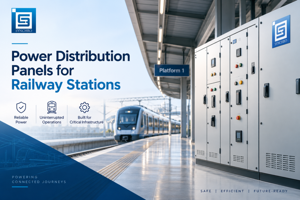
A railway station is one of the more demanding environments an electrical panel can be asked to work in, and it rarely gets discussed that way.
The load never really switches off. The panel room sits close to an area where trains pass, so there is constant low-frequency vibration. Dust from platforms and approach roads finds its way into every enclosure. During monsoon, humidity climbs and drainage gets tested. Maintenance has to happen inside short night windows because you cannot shut down a station to change a breaker. And the consequences of a distribution failure are not measured in production loss, they are measured in passenger safety and public inconvenience.
Over the years, working on power distribution panels for government and public infrastructure projects, including municipal utilities and large public buildings, one pattern stands out. The stations that run without incident are the ones where the distribution scheme was designed around how the station actually operates, not just around a connected load figure on a drawing.
This article covers how power distribution at a railway station is typically structured, which panels do what, and the design decisions that determine whether the installation is dependable a decade from now.
Why Railway Station Power Distribution is Different
Before looking at panels, it helps to be clear about what makes this application unusual.
Traction and non-traction supply are separate systems. The 25 kV overhead traction supply that moves trains is an entirely separate domain with its own substations and switching. Station power distribution panels deal with the auxiliary or non-traction supply: lighting, fans, pumps, lifts, escalators, air conditioning, signalling and telecom, public address, display boards, CCTV, ticketing systems and commercial areas. When someone specifies a power distribution panel for a station, this is almost always what they mean.
Loads are mixed and awkward. A station has a very large lighting load spread over a wide area, a cluster of motor loads that start and stop frequently, sensitive electronic loads that will not tolerate a dip, and commercial loads that belong to third-party licensees and need separate metering. These behave differently and cannot all be treated the same way.
Some loads are life-safety loads. Platform lighting, emergency lighting, escalator and lift controls, fire systems, signalling and public address are not conveniences. The distribution scheme has to guarantee their supply even when everything else is down.
Public access is a real design constraint. Panels in circulating areas, on platforms or in concourses are within reach of thousands of people daily. Enclosure security, degree of protection and the absence of accessible live parts are not optional refinements.
Maintenance windows are short. Most stations offer a few hours at night, at best. Panels must be built so that a faulty component can be isolated and replaced quickly, without dismantling half the assembly.
The Typical Power Distribution Architecture at a Station
The arrangement varies with station category, but the backbone is consistent.
- HT incomer and switching. Supply arrives at 11 kV, 22 kV or 33 kV from the distribution licensee or the railway’s own network. This terminates in an HT panel, usually a VCB panel built around a vacuum circuit breaker, with associated protection relays, CTs, PTs and metering. Larger stations have two incomers with an interlocked changeover so that loss of one source does not take the station down.
- Transformation. One or more distribution transformers step the supply down to 415 V. Capacity is usually split across multiple transformers rather than one large unit, so that a transformer outage removes part of the station load, not all of it.
- Main LT distribution. The transformer secondary feeds a PCC panel, the main power control centre for the station. This is the heart of the electrical distribution system: it takes the incoming supply, provides the main protection, and distributes onward to every sub-distribution point. On a two-transformer scheme, the PCC panel carries two incomers and a bus coupler with a mechanical and electrical interlock so that only two of the three breakers can be closed at any time.
- Backup generation. A DG set with an AMF panel or an ATS panel provides supply to the essential bus on mains failure. The automatic transfer switch logic, the changeover timing and the neutral switching arrangement all need to be settled at the design stage, not improvised during commissioning.
- Sub-distribution. From the PCC, feeders run to an MCC panel for motor loads such as water pumps, sump pumps, lift and escalator drives and air handling units. Separate lighting distribution panels serve platforms, concourse, circulating area, foot over bridges and building lighting. Additional distribution panels serve signalling and telecom rooms, ticketing, and commercial zones.
- Power factor correction. An APFC panel on the main bus corrects the lagging power factor created by the motor load and keeps the station within the licensee’s power factor requirements, avoiding penalties and reducing distribution losses.
- Metering. A meter panel and sub-meters give visibility on consumption by zone and allow commercial licensees to be billed accurately. This matters more than most people expect during procurement and becomes an accounting headache when it is left out.
- Rooftop solar, where applicable. Many stations now have rooftop PV. That brings solar ACDB and DCDB boxes, surge protection devices on both DC and AC sides, and an interface back into the LT bus with appropriate protection and metering.
In multi-level or redeveloped stations, an L.T. bus duct or sandwich bus duct is often used for the riser between the transformer and the main panel, or for vertical distribution up through the building. It handles high currents in less space than parallel cable runs and is easier to tap at each floor.
Panel-by-Panel: What Each One Has to Get Right
PCC Panel (Power Control Centre)
This is where redundancy is engineered. Key decisions:
- Correct fault level rating, verified against the transformer impedance and the utility fault level, with adequate short circuit withstand capacity for the busbar system
- Form of separation. Form 3b or Form 4b is appropriate where feeders must be worked on while the busbar remains live, which is the normal situation at a station
- Draw-out ACBs on incomers and major feeders, so a breaker can be racked out and swapped within a night block
- Discrimination between the incomer and outgoing feeders, so a fault on one platform feeder does not black out the whole station
- Spare feeders. Twenty to thirty percent spare capacity is not waste. Stations get redeveloped, escalators get added, EV charging arrives, commercial space expands
MCC Panel
Serves pumps, lifts, escalators and HVAC. Feeder-wise protection and overload settings need to match the actual motor data, not assumed ratings. Where variable speed control is used on pumps or AHUs, the harmonic effect on the rest of the electrical distribution system should be considered at the design stage rather than diagnosed later.
Lighting Distribution Panel
Often treated as the simplest panel in the station and it is usually the one that causes the most nuisance tripping. Modern LED lighting draws high inrush current at switch-on. A lighting distribution panel sized on steady-state current alone will trip every time the platform lights come on. Circuit grouping also matters: platform lighting should be split so that a single circuit failure never darkens an entire platform.
APFC Panel
Sizing needs to reflect the load profile across the day, which at a station swings widely between peak train hours and the early morning lull. Stage sizing, switching sequence, capacitor discharge time and contactor selection determine whether the panel holds target power factor or hunts continuously.
AMF and ATS Panel
The essential bus depends entirely on this panel working the first time, after months of sitting idle. Changeover timing, DG start logic, fail-to-start alarms and periodic auto-test functionality should all be specified explicitly.
VCB Panel
On the HT side, protection settings must coordinate with the utility’s upstream protection. Relay setting sheets, CT ratios and tripping schemes need to be agreed with the supply authority before commissioning, not negotiated afterwards.
Essential and Non-Essential: Getting the Segregation Right
The single most useful thing a designer can do early is split the station load into clear categories:
Essential and life-safety: emergency and platform lighting, signalling and telecom, fire detection and firefighting pumps, public address, CCTV, lift and escalator controls for evacuation, station control room. These stay on DG backup, with UPS support for the electronics that cannot tolerate even a short changeover gap.
Important but interruptible: general lighting, fans, water pumps, ticketing counters, waiting halls.
Non-essential: commercial shops, retiring room air conditioning, advertising displays, non-critical HVAC.
This segregation drives the busbar arrangement inside the PCC panel, the DG sizing, and which feeders sit on which section. Getting it wrong means either an oversized generator running a coffee stall at 2 am, or platform lighting that fails during a power cut. Both happen, and both are avoidable.
Enclosure and Environmental Design
Panel construction choices deserve more attention than they usually get in a station project.
Ingress protection IP rating. Indoor panel rooms typically call for IP54. Panels near platform edges, in semi-covered areas or exposed to driven rain need IP55 or higher, and the gasket and door design need to actually deliver it, not just claim it.
Material. In coastal locations, CRCA sheet with standard powder coating will not last. Either specify a higher coating specification or move to stainless steel for exposed enclosures.
Vibration. Panels near running lines experience continuous low-level vibration. Busbar support spacing, component mounting and terminal torque all matter more here than in a typical factory installation.
Rodent and dust ingress. Cable entries need proper sealing and gland plates. Open bottom entries into a cable trench are a recurring source of trouble.
Plinth height and drainage. Panel rooms flood. A raised plinth and a drained trench cost very little at construction stage and save an entire panel later.
Access and security. Lockable doors, no accessible live parts, clear danger marking, and isolation arrangements that allow safe working by station staff.
Standards and Compliance
Panels for railway station applications are generally expected to comply with IS 8623 and IEC 61439-1 and 61439-2 for low-voltage switchgear and controlgear assemblies, with earthing designed to IS 3043 and installation practices following CEA safety regulations. Project specifications frequently also reference RDSO or zonal railway requirements, and fire safety provisions follow the National Building Code where the station building is covered.
A type tested panel design, verified against IEC 61439 for temperature rise, short circuit withstand strength, clearances and degree of protection, simplifies inspection considerably. Routine test reports for each individual panel, covering dielectric testing, insulation resistance and functional verification, should be part of the handover documentation. Where the project involves third-party inspection, agreeing the test protocol at the order stage saves a great deal of time later.
Common Mistakes on Station Projects
- Sizing only for present load. Stations grow. Panels sized exactly to today’s connected load become the bottleneck at the first upgrade.
- Ignoring the lighting inrush problem and then blaming the breakers.
- A single transformer and a single incomer at a station where a four-hour outage is unacceptable.
- Locating the panel room where flooding or heat build-up is likely, with no ventilation or cooling provision.
- No sub-metering, discovered only when commercial licensees have to be billed.
- Poor documentation handover. Six months later nobody knows which feeder serves which circuit, and every fault becomes a search exercise.
- Treating the DG changeover as commissioning-day work rather than designed logic.
Procurement Checklist for Station Projects
If you are sourcing power distribution panels for a station, ask prospective electrical panel manufacturers:
- Will GA drawings, single line diagrams and schematics be submitted for approval before procurement begins?
- What form of separation is offered, and is the fault level rating substantiated?
- Is a type tested design available for the relevant panel type, and can the certificate be provided?
- What is the declared ingress protection IP rating, and how is the enclosure specified for the actual installation environment?
- How many spare feeders and how much spare busbar capacity are included?
- What routine tests are performed, and what test documentation is handed over?
- Is factory acceptance testing supported with the customer or consultant witnessing?
- What support is available during installation, commissioning and afterwards?
How Synchro Electricals Works on Infrastructure Projects
We manufacture LT and HT panels from our facility in Rajkot for industrial, solar, commercial and government infrastructure projects, including municipal water treatment installations and large commercial complexes where continuous supply is non-negotiable.
Every panel is engineered from the load schedule and site conditions rather than picked from a catalogue, with drawings approved in writing before a single component is ordered. Each panel undergoes high-voltage testing, insulation resistance testing and functional testing before dispatch, and the test report travels with it. We are ISO 9001:2015 certified, build to IS standards with IEC compatibility, and our team stays available through commissioning and beyond.
For station projects, we would rather be involved while the distribution scheme is still being finalised. The decisions that matter most, on redundancy, segregation and spare capacity, are made long before anyone starts building a panel.
Closing Thought
Station power distribution rewards planning and punishes shortcuts. The load will grow, the environment will be harsher than the drawing suggests, and the maintenance window will always be shorter than anyone would like. Panels designed with those three realities in mind tend to be the ones nobody has to think about again.
If you are working on a station project, a depot, or any public infrastructure installation and want the distribution scheme reviewed before panels are ordered, our engineering team is available to help.
Synchro Electricals Pvt. Ltd. Plot No. 35–40, Pushti Parishar Industrial Area, Ravki, Taluka Lodhika, Rajkot, Gujarat 360004 Phone: +91 96019 65426 | Email: info@synchroelectricals.in
FAQS:-
What is the difference between traction and non-traction power distribution at a station? Traction supply powers the trains through the overhead equipment at 25 kV and is handled by dedicated traction substations. Non-traction or auxiliary supply powers everything else at the station, and that is what station power distribution panels serve.
Which panel is the main one at a railway station? The PCC panel. It receives the transformer output, provides main protection, and distributes to all sub-distribution panels across the station.
How much backup capacity should a station DG cover? It depends on the essential load, not the total connected load. Once lighting, signalling, pumps, fire systems, lifts and escalators required for safe operation are identified, the DG and the essential bus are sized around that, with a margin for future addition.
What IP rating is appropriate for station panels? IP54 is typical for panels in a dedicated indoor panel room. Semi-exposed or platform-side locations generally need IP55 or better, and coastal stations need a corrosion-resistant enclosure specification as well.
Can rooftop solar be integrated into an existing station distribution system? Yes, through solar ACDB and DCDB boxes with appropriate surge protection devices and a properly protected interface into the LT bus. The existing panel’s spare capacity and protection coordination need to be reviewed before the tie-in is designed.