Every industrial control panel we have ever reworked in the field had one thing in common: the failure was never really about the components. It was about how those components were wired together – spacing that ignored heat rise, ducts crammed past capacity, wires with no numbering, or a control cable routed alongside a 415V power feed picking up enough noise to trip a PLC input at random. The switchgear was often fine. The wiring design underneath it wasn’t.
At Synchro Electricals, we have been designing and building LT and HT control panels out of our Rajkot facility since 2018 — over 500 projects across industrial plants, EPC solar sites, and government infrastructure, with more than 8GW of solar capacity running through panels we’ve supplied. This guide is built from that floor experience, not a rewrite of a standards document. If you’re a plant engineer, EPC procurement lead, or panel builder trying to get wiring design right the first time, here’s what actually matters.
Why Wiring Design Decides Whether a Panel Survives the Field
A panel’s schematic can be perfect and the build can still fail inspection or fail in service, because wiring design sits at the intersection of three things that generic catalogue panels almost never get right together: thermal management, electromagnetic separation, and serviceability. We’ve walked into a Gujarat packaging plant where recurring motor downtime traced back to a Motor Control Centre panel with no separation between power and signal wiring — the fix wasn’t a new motor starter, it was a rewire. We’ve also seen a 50MW solar plant’s ACDB distribution held up at commissioning purely because wire identification didn’t match the as-built drawings the EPC contractor needed to sign off.
Good wiring design prevents both problems: it protects the panel from the electrical stresses it will actually see in operation, and it protects the technician who has to open that panel five years from now with no memory of how it was built.
The Standards That Govern Panel Wiring Design
Before any wiring decision gets made, the applicable standard has to be settled — because it changes clearance distances, color coding, and documentation requirements.
| Standard | Scope | Where it applies |
|---|---|---|
| IEC 61439-1 / 61439-2 | General rules and requirements for low-voltage switchgear and controlgear assemblies (PCC, MCC, distribution boards) | International — increasingly the default reference across Indian panel manufacturing |
| IS 8623 | India’s legacy standard for factory-built assemblies, historically aligned to IEC 60439 | Being phased toward IEC 61439-aligned practice across Indian industry |
| IEC 60664-1 | Insulation coordination — clearance and creepage distances between live parts | Governs busbar and terminal spacing globally |
| UL 508A / NEC Article 409 | Industrial control panel construction and wiring | North America — relevant for export-facing panel builders |
The practical takeaway for anyone sourcing panels in India: ask specifically whether the panel is IEC 61439 compliant, not just “IEC compatible.” Compliance means the assembly itself has been verified — through routine and, where applicable, type testing — not just that the individual breakers and contactors inside it carry IEC-rated components. A panel can be full of correctly certified parts and still fail as an assembly if the internal wiring, clearances, and thermal design weren’t verified together.
Core Wiring Design Best Practices
1. Design the Layout Before You Route a Single Wire
Component placement determines everything downstream. Leave real spacing between heat-generating devices — VFDs, contactors, resistors — so heat dissipates instead of stacking. A panel that looks efficient on paper but runs hot in the field will shorten the life of every terminal inside it. Layout also has to account for future work: leave room to add a breaker or terminal block later, because facilities expand and panels that can’t accommodate a spec change get replaced entirely rather than modified.
2. Segregate Power and Control Wiring
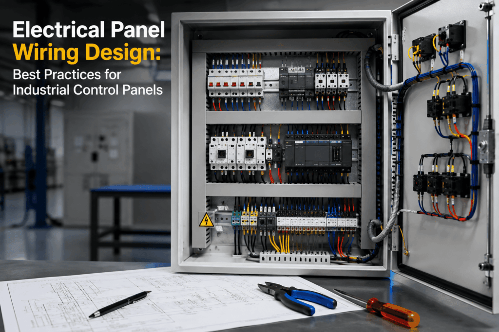
Route power wiring (415V/690V feeds, motor leads) and control/signal wiring (PLC I/O, 24V DC, communication cables) in separate wire ducts. Running them together is one of the most common causes of nuisance PLC faults and signal drift we see in field service calls — the power wiring induces electromagnetic interference into low-voltage control circuits that were never shielded for it. If ducts must cross, cross at 90 degrees, never run parallel for any distance.
3. Size Wire Ducts for the Panel’s Full Life, Not Just Day One
A wire duct filled to capacity on delivery day leaves zero room for future modification and makes every future wire pull a fight. The working rule we hold our design team to: fill duct to no more than 40–50% of capacity at initial build. It costs marginally more enclosure space upfront and saves hours of rework later.
4. Respect Busbar Clearance and Creepage Distances
Clearance (through air) and creepage (along a surface) between conductors at different potentials is not a judgment call — it’s governed by IEC 60664-1 based on rated voltage and pollution degree. For a typical 400V system under pollution degree 2 (standard industrial environment), expect roughly 14–20mm phase-to-phase clearance and around 10mm phase-to-earth as a baseline, though the exact figures depend on impulse withstand voltage and the specific assembly design. Cutting these distances to fit more busbar into a smaller enclosure is the single fastest way to fail a dielectric test — or worse, to have a genuine arc-flash risk sitting in a live panel.
5. Use Ferrules and Controlled Termination, Not Just Bare Stranded Ends
Ferrule-terminated conductors give a tighter, more consistent contact surface than a bare stranded wire twisted into a terminal — which matters enormously in high-vibration environments like packaging lines or DG-set-adjacent panels, where loose terminations are a leading cause of intermittent faults. Torque-controlled termination, checked against the terminal manufacturer’s spec, should be standard practice on every panel that leaves the factory, not an optional step reserved for premium orders.
6. Build a Wire Numbering System That Survives Time
Every wire should carry a permanent, legible number that matches the wiring diagram, at both ends. This single practice is what separates a panel that gets fixed in twenty minutes from one that causes a four-hour production outage while a technician traces an unlabeled cable by hand. Labels fade and get replaced with nothing — specify wear-resistant, permanent marking at the design stage, not as an afterthought during assembly.
7. Color-Code Conductors to the Destination Country’s Standard — Don’t Assume
Wire and busbar color coding is not universal. IEC-based standards require phase, neutral, and protective conductors to be unambiguously identifiable but leave some flexibility on exact colors inside the enclosure; North American codes under NEC are considerably more prescriptive, including specific rules like marking a high-leg conductor permanently orange on certain delta systems. Any panel builder shipping across regions — which matters directly for Indian manufacturers serving export EPC clients — has to verify the destination country’s code before wiring, not after the panel is built.
8. Design the Grounding System as Carefully as the Power Path
Grounding isn’t a bolt-on step at the end of assembly — it needs to be part of the wiring design from the start, with dedicated ground busbars, verified continuity, and safety margins that meet or exceed the applicable standard. Under-engineered grounding is invisible until there’s a fault, at which point it’s the difference between a tripped breaker and a safety incident.
9. Document the Panel as Thoroughly as You Wire It
A complete drawing package — schematics, layout drawings, bill of materials, wire list, and a symbol legend for anything shop-specific — should leave the factory with every panel. Assume the next person to open this panel has no memory of how it was built; that assumption is what makes documentation useful five or ten years down the line, not just at commissioning.
10. Test Before It Leaves the Factory, Not After It Arrives on Site
Wiring design isn’t verified until it’s tested. High-voltage (dielectric) testing, insulation resistance testing, and full functional testing should happen on every panel, with a test report issued as standard documentation — not a premium add-on. This is also the stage where wiring errors that visual inspection misses (a swapped phase, a marginal clearance, a loose termination) actually get caught, before they become a site commissioning delay.
Wiring Considerations by Panel Type
Wiring priorities shift depending on what the panel does:
- PCC (Power Control Centre) Panels — incoming power distribution demands generous busbar clearance and careful current-carrying capacity planning, since a PCC panel is the central point every downstream circuit depends on.
- MCC (Motor Control Centre) Panels — motor starter wiring needs strict power/control segregation and vibration-resistant termination, since MCCs typically sit closest to rotating machinery.
- VFD Panels — variable frequency drives generate significant electrical noise; shielded cable, dedicated grounding, and physical separation from control wiring are non-negotiable here.
- APFC Panels — capacitor bank wiring needs careful attention to switching transients and thermal spacing between capacitor stages.
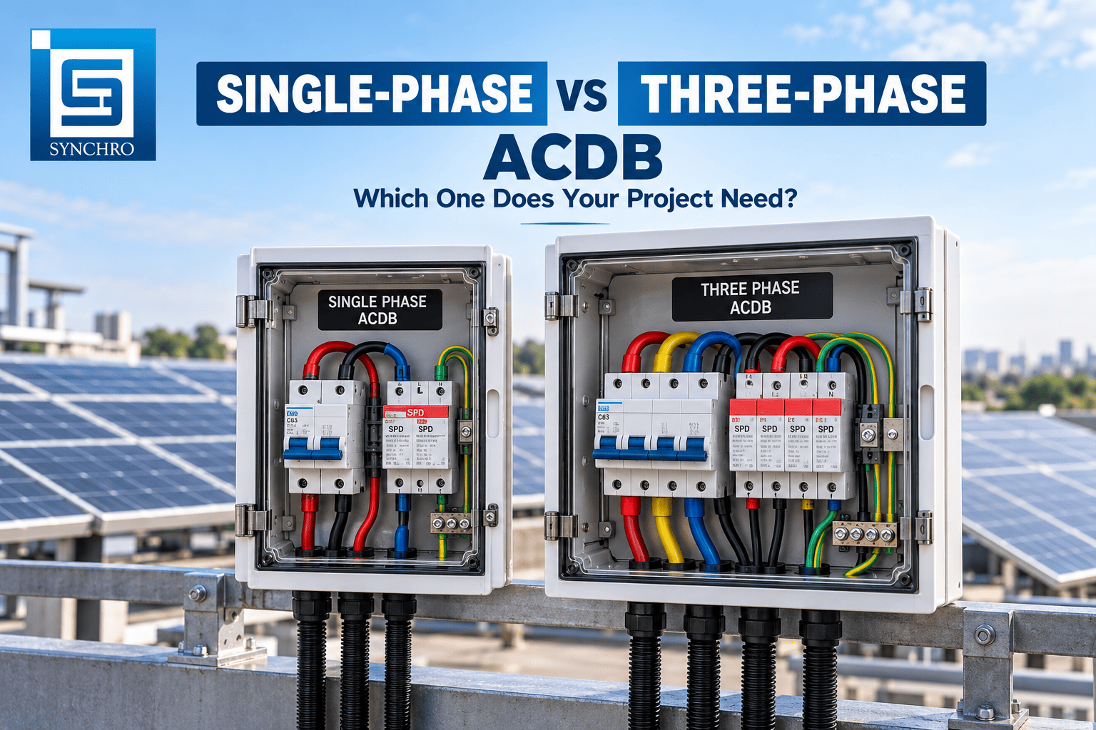
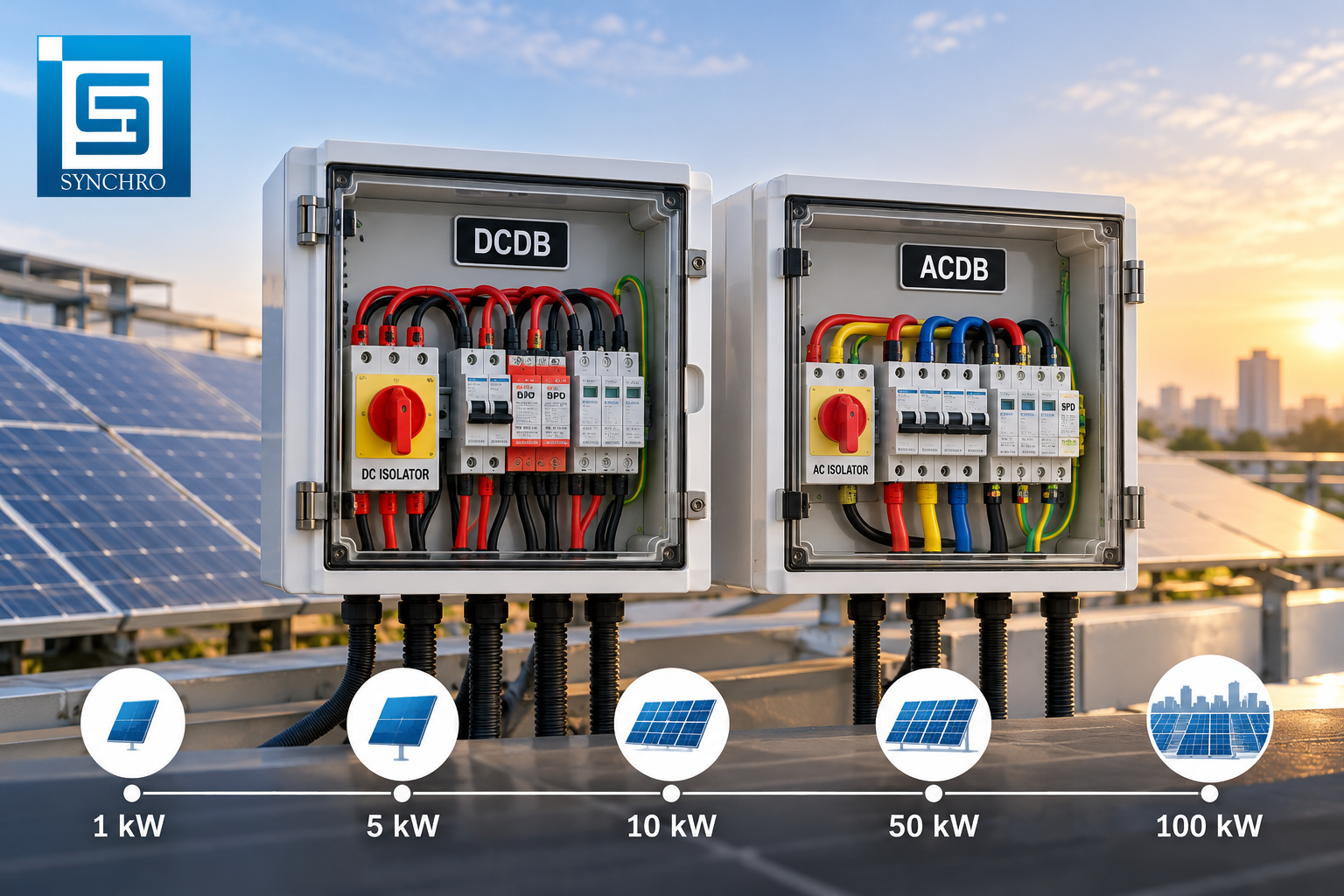
- Solar ACDB/DCDB Boxes — DC-side wiring carries its own polarity marking and clearance rules distinct from AC distribution, and field exposure adds environmental sealing requirements on top of the electrical design.
If you’re unsure which panel type your project actually needs — a question we field constantly from first-time EPC clients — that’s a design conversation worth having before wiring specs are even drafted, not after.
A Practical Wiring Design Checklist
- Layout finalized with thermal spacing and future-expansion room before wiring begins
- Power and control wiring routed in separate, appropriately sized ducts
- Duct fill kept at 40–50% of capacity
- Busbar clearance and creepage verified against IEC 60664-1 for the rated voltage and pollution degree
- Ferrules used on all stranded terminations, torque-checked
- Every wire numbered at both ends, matching the wiring diagram
- Color coding verified against the destination country’s standard
- Grounding system designed with dedicated busbars and verified continuity
- Complete drawing package prepared: schematics, BOM, wire list, symbol legend
- Dielectric, insulation resistance, and functional tests completed with a signed test report
How We Apply This at Synchro Electricals
Every panel we build follows a four-step process specifically because wiring design failures are almost always design-stage failures, not assembly-stage ones: we start by understanding the actual load and application, then submit full technical drawings for written approval before a single component is ordered, then fabricate under an ISO 9001:2015-certified process with high-voltage and functional testing on every unit, and finally deliver with complete documentation and commissioning support. Our 800VAC solar panel line carries full type-test certification through CPRI, and our manufacturing is IEC-compatible across our PCC, MCC, VFD, APFC, and Solar ACDB/DCDB ranges.
If you’re sourcing a panel for an industrial facility, EPC solar project, or infrastructure build and want the wiring design reviewed by an engineering team before manufacturing starts, get in touch with our team — we respond to technical inquiries within 24 hours with an actual recommendation, not a generic quote.
Frequently Asked Questions
What is the most common wiring mistake in industrial control panels?
Routing power and control wiring in the same duct or bundle. It’s the single most frequent cause of nuisance PLC faults and signal interference we see when troubleshooting panels built by other shops.
Is IEC 61439 mandatory for panels manufactured in India?
It isn’t universally mandatory by law, but most EPC contractors and industrial specifications now require IEC 61439-compliant assemblies, and it has effectively replaced the older IS 8623 framework as the practical benchmark for quality panel manufacturing in India.
How do I know if a panel manufacturer’s wiring design is actually reliable?
Ask for the test report format they issue as standard – dielectric, insulation resistance, and functional test results – and ask to see a sample wiring diagram with wire numbering. A manufacturer who treats these as standard deliverables, not paid extras, is signaling a mature wiring design process.
What’s the difference between wiring design for a PCC panel and an MCC panel?
A PCC panel’s wiring design centers on distribution — busbar sizing and clearance for the incoming feed. An MCC panel’s wiring design centers on motor circuits — segregation between power feeding the motor and control signals governing start/stop/protection logic.
This guide reflects manufacturing practices at Synchro Electricals, an ISO 9001:2015-certified electrical panel manufacturer based in Rajkot, Gujarat, building IEC-compatible LT and HT panels for industrial, solar, and infrastructure projects across India since 2018. For panel-specific wiring guidance, contact our engineering team at +91 96019 65426 or info@synchroelectricals.in.