A well-designed electrical system is only as safe as its grounding and fault protection strategy. Circuit breakers and protection relays get most of the attention during panel design, but electrical panel earthing design is what actually provides a safe path for fault currents and keeps both equipment and personnel out of danger.
In utilities, infrastructure projects, manufacturing facilities, and commercial installations, electrical control panels are critical points of power distribution and system control. A ground fault in a panel without an effective earthing system means fault current starts finding its own way to earth – through equipment frames, enclosures, cable trays, anything conductive nearby. That’s when things get dangerous.
This is why electrical panel earthing design and ground fault protection methods are treated as non-negotiable requirements in modern power systems engineering.
When Electricity Finds the Wrong Path
Normal operation is simple enough – current flows through designated conductors and returns through the intended circuit path. A ground fault is what happens when that current escapes. It moves toward earth through equipment frames, panel enclosures, cable trays, or whatever conductive structure is closest.
Even a relatively small ground fault creates dangerous touch voltages on metallic surfaces. In higher-capacity systems, the fault currents involved are large enough to cause serious damage to switchgear, cables, and electrical control panels.
An effective electrical panel grounding system gives fault current a low-resistance path to earth – controlled, intentional, and fast enough that protective devices can detect and clear the fault before it develops further. Without that, protective devices may not operate correctly, and hazardous conditions persist.
Earthing Is More Than Connecting a Wire to the Ground
A lot of installations treat earthing as a single connection to a ground rod. That’s not earthing design — that’s a starting point at best.
Proper electrical panel earthing design requires a coordinated approach across multiple grounding components. Inside an electrical control panel, every exposed metallic part needs to be bonded together and tied into the facility’s earthing network. The result is an equipotential system that keeps voltage differences under control during fault conditions.
How well that system performs depends on soil resistivity, conductor sizing, grounding electrode configuration, and the integrity of bonding throughout the installation. Poor grounding raises system impedance, slows down fault current return, and delays fault clearing – all of which make a dangerous situation worse.
Designing Earthing Systems for Reliable Fault Current Dissipation
Earthing system design starts with one question: what is the maximum fault current this installation could see? Grounding conductors have to carry that current safely for as long as it takes protective devices to operate.
Engineers typically work through:
- Fault current levels within the electrical network
- Ground conductor sizing requirements
- Earthing electrode resistance values
- Bonding between panel components and structural elements
A properly designed grounding system improves safety and adds to the overall reliability of electrical control panels used in utility and infrastructure projects. For critical installations – substations, water treatment facilities, transportation infrastructure – achieving low earth resistance values isn’t optional, it’s a core design objective.
How Ground Fault Protection Complements Earthing Design
Earthing handles the fault current once a fault exists. Ground fault protection is what catches it early.
Modern electrical control panels incorporate ground fault protection schemes that monitor current flow continuously. When leakage current appears, the protection system acts before the fault grows into something larger.
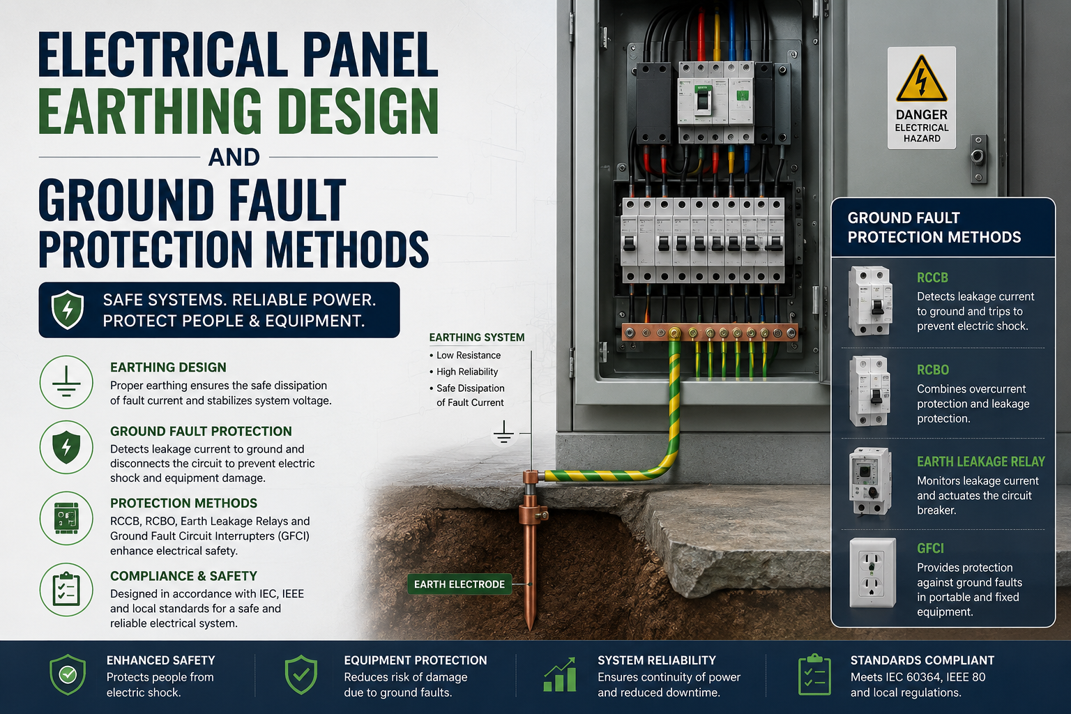
Common ground fault protection methods in use today include:
- Residual current monitoring
- Earth fault relays
- Ground fault circuit interrupters (GFCI)
- Differential protection systems
Which method gets selected depends on voltage level, system configuration, and the operational demands of the specific installation. The point is that earthing systems and ground fault protection devices have to work together – one provides the path, the other triggers the response. Neither does the full job alone.
The Challenge of Ground Faults in Large Infrastructure Projects
Utilities and infrastructure facilities run extensive electrical networks across large geographic areas. Long cable runs, multiple distribution points, and varying soil conditions all make grounding systems considerably more complex than in a standard commercial installation.
Ground fault protection in these environments requires careful coordination so that the protective device closest to the fault operates first. That selectivity matters – it contains the problem, keeps healthy sections of the network running, and avoids shutdowns that affect far more than the faulted circuit.
As infrastructure projects rely more heavily on automation and digital control systems, effective electrical panel grounding and protection systems become even more critical. Sensitive electronics can be affected by grounding issues well before any major fault occurs, which means problems show up in the control system before they’re traceable to a grounding deficiency.
Building Safer Electrical Control Panels
At Synchro Electricals, reliable earthing is a core part of electrical panel performance — not a compliance checkbox at the end of a project. During the design of electrical control panels, our engineering team evaluates grounding arrangements, conductor sizing, bonding requirements, and protection coordination to ensure fault current is managed safely from the start.
Integrating effective electrical panel earthing design with appropriate ground fault protection methods is how we deliver panels that hold up operationally and electrically across demanding utility and infrastructure applications.
A Foundation for Electrical Safety
Most electrical problems that could have been prevented trace back to grounding issues that nobody caught until a fault made them obvious. A properly engineered electrical panel earthing system gives fault current somewhere safe to go, protective devices something to work with, and personnel a meaningful layer of protection.
Pair that with well-coordinated ground fault protection methods and the electrical control panel holds up – under normal conditions and abnormal ones. For utilities, infrastructure projects, and industrial facilities, getting grounding right from the design stage remains one of the highest-value decisions in the entire electrical system.
FAQs
1. What is the purpose of earthing in an electrical control panel?
Earthing gives fault current a safe, controlled path to ground – protecting equipment from damage and keeping personnel away from dangerous touch voltages.
2. Why is electrical panel earthing design important?
Because a poorly designed earthing system slows fault clearing, raises touch voltage risks, and undermines the reliability of the entire panel. Getting it right at the design stage prevents problems that are much harder to fix later.
3. What causes a ground fault in an electrical system?
A ground fault happens when current leaves its intended path and flows to earth through equipment, exposed metal parts, or structural elements that weren’t designed to carry it.
4. What devices are used for ground fault protection?
Earth fault relays, residual current devices, GFCIs, and differential protection systems are the most common. Selection depends on the voltage level and configuration of the specific installation.
5. How does grounding improve electrical panel safety?
It gives fault current a defined, low-resistance path back to earth, which lets protective devices operate quickly, isolate the fault, and stop the hazardous condition before it causes harm.